Replacing core hole closing cover in cylinder crankcase
|
|
||||
|
01—140 Replacing core hole closing cover in cylinder crankcase
|
||||
|
|
||||
|
Special tool
|
||||
|
|
||||
|
Mandrel for knocking-in core hole closing covers
|
102 589 00 15 00
|
|||
|
11004-962S
|
||||
|
|
||||
|
Note
|
 |
|||
|
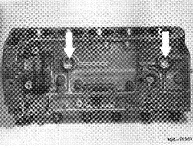
Core holes in cylinder crankcase are closed with sheet metal covers (34 mm dia.).
Replace leaking closing covers on principle.
At the right (driving direction) the closing plug (M 38 x 1.5) remains in place.
|
||||
|
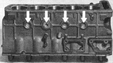
Driving direction left
|
||||
|
|
||||
|
This core hole can be used to insert cooling water preheater.
|
 |
|||
|
|
||||
|
Driving direction right
|
||||
|
|
||||
|
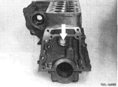
Transmission end
|
 |
|||
|
|
||||
|
01.8-140/1 F2
|
||||
|
|
||||
|
|
|||
|
Replacement
|
 |
||
|
1 Completely drain coolant.
2 Remove components which obstruct access (e.g. transmission, intermediate flange, injection pump etc.).
|
|||
|
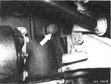
Drain plug on cylinder crankcase
|
|||
|
|
|||
|
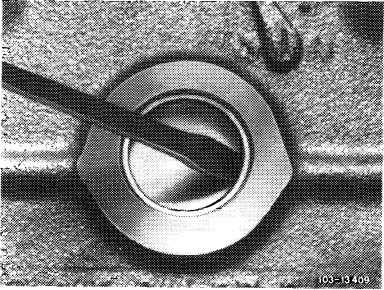
3 Position a chisel with a narrow blade or a screwdriver into deep drawn edge of closing cover.
|
 |
||
|
|
|||
|
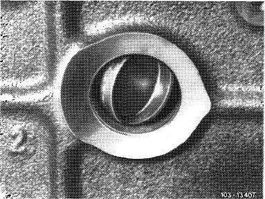
4 Carefully knock closing cover on one side down until cover has turned around its own longitudinal axis (approx. 90°).
|
 |
||
|
|
|||
|
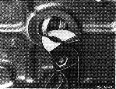
5 Position water pump pliers against flange of projecting section and pull out closing cover.
|
 |
||
|
|
|||
|
01.8-140/2 F2
|
|||
|
|
|||
|
|
|||
|
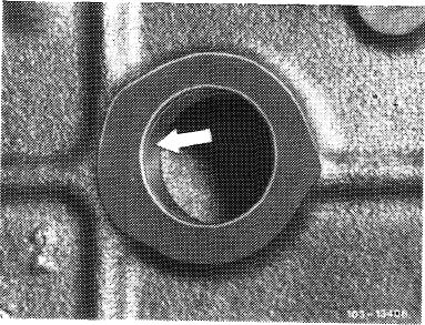
6 Thoroughly clean core hole from residue. Sealing surface should be free of grease (arrow).
7 Coat core hole with sealing glue, part no. 002 989 94 71.
|
 |
||
|
|
|||
|
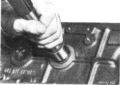
8 Knock-in new closing cover by means of mandrel.
9 Attach removed components.
10 Add coolant.
Note: The sealing glue should cure for approx. 45 minutes before adding coolant.
|
 |
||
|
|
|||
|
11 Run engine warm and check for leaks.
|
|||
|
|
|||
|
01.8-140/3 F2
|
|||
|
|
|||