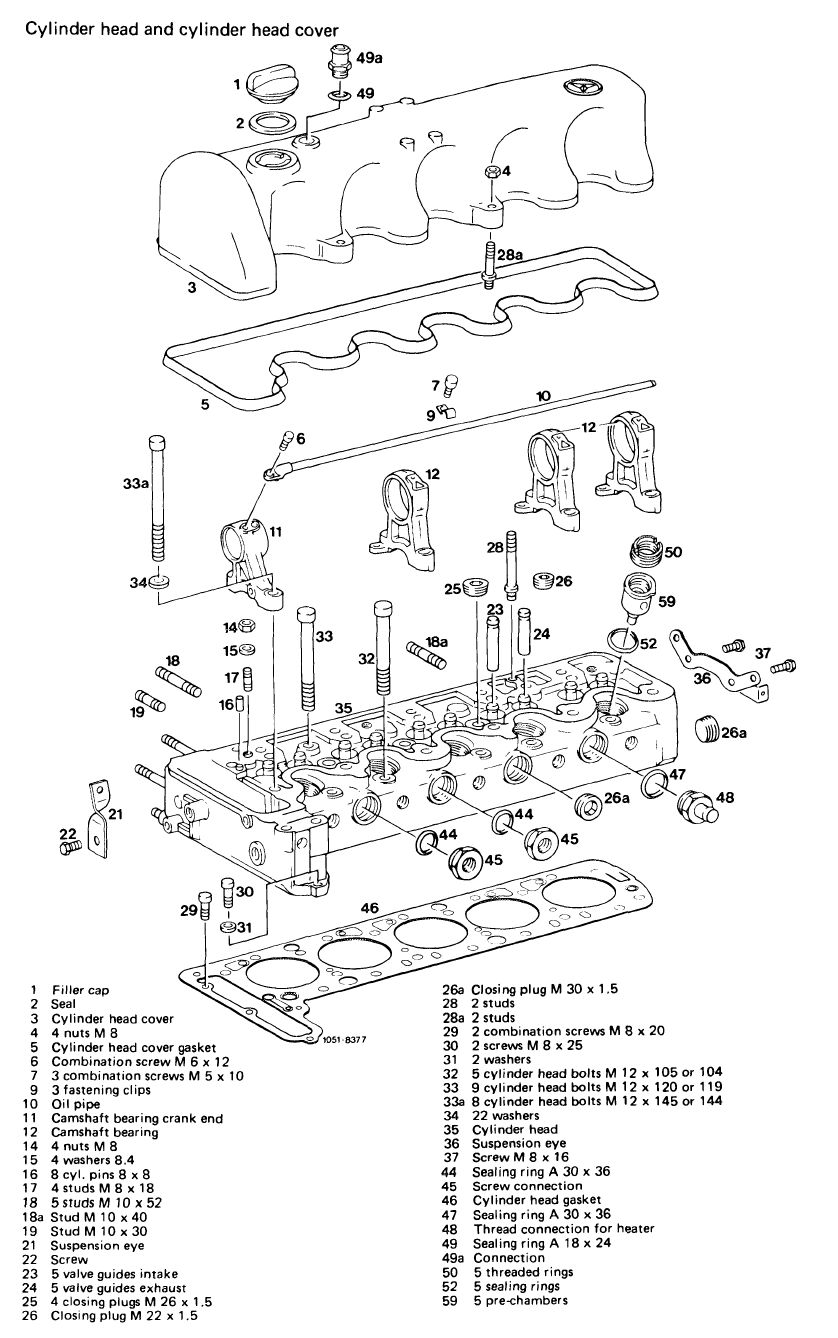
Removal and installation of cylinder head
|
|
||||||||||||||||||||||||||||||||||||||||||||||||||||||||||||||||||||||||||||||||
|
01—415 Removal and installation of cylinder head
|
||||||||||||||||||||||||||||||||||||||||||||||||||||||||||||||||||||||||||||||||
|
|
||||||||||||||||||||||||||||||||||||||||||||||||||||||||||||||||||||||||||||||||
|
Valve clearance
|
with engine cold (appr. 20 °C) with engine warm (appr.60°C±15°C)
|
|||||||||||||||||||||||||||||||||||||||||||||||||||||||||||||||||||||||||||||||
|
|
||||||||||||||||||||||||||||||||||||||||||||||||||||||||||||||||||||||||||||||||
|
Intake
|
0.101;
|
0.151’
|
||||||||||||||||||||||||||||||||||||||||||||||||||||||||||||||||||||||||||||||
|
|
||||||||||||||||||||||||||||||||||||||||||||||||||||||||||||||||||||||||||||||||
|
Exhaust
|
0.35
|
0.40
|
||||||||||||||||||||||||||||||||||||||||||||||||||||||||||||||||||||||||||||||
|
|
||||||||||||||||||||||||||||||||||||||||||||||||||||||||||||||||||||||||||||||||
|
’ 0.05 mm higher during lasting outside temperatures below-20 C.
|
||||||||||||||||||||||||||||||||||||||||||||||||||||||||||||||||||||||||||||||||
|
|
||||||||||||||||||||||||||||||||||||||||||||||||||||||||||||||||||||||||||||||||
|
Timing at 2 mm valve lift
|
||||||||||||||||||||||||||||||||||||||||||||||||||||||||||||||||||||||||||||||||
|
|
||||||||||||||||||||||||||||||||||||||||||||||||||||||||||||||||||||||||||||||||
|
||||||||||||||||||||||||||||||||||||||||||||||||||||||||||||||||||||||||||||||||
|
|
||||||||||||||||||||||||||||||||||||||||||||||||||||||||||||||||||||||||||||||||
|
1 ) The camshaft code number is punched into rear end of camshaft.
2) (ui^) up to model year 1979
3) (usa) model year 1980
4 ) Camshaft made of chilled cast iron
|
||||||||||||||||||||||||||||||||||||||||||||||||||||||||||||||||||||||||||||||||
|
|
||||||||||||||||||||||||||||||||||||||||||||||||||||||||||||||||||||||||||||||||
|
Tightening torques
|
Nm
|
|||||||||||||||||||||||||||||||||||||||||||||||||||||||||||||||||||||||||||||||
|
|
||||||||||||||||||||||||||||||||||||||||||||||||||||||||||||||||||||||||||||||||
|
Nuts for cylinder head cover
|
15
|
|||||||||||||||||||||||||||||||||||||||||||||||||||||||||||||||||||||||||||||||
|
|
||||||||||||||||||||||||||||||||||||||||||||||||||||||||||||||||||||||||||||||||
|
Hex. socket cylinder head screws (with engine cold)
|
|
|||||||||||||||||||||||||||||||||||||||||||||||||||||||||||||||||||||||||||||||
|
Hex. socket cylinder head screws (with engine cold)
|
||||||||||||||||||||||||||||||||||||||||||||||||||||||||||||||||||||||||||||||||
|
|
||||||||||||||||||||||||||||||||||||||||||||||||||||||||||||||||||||||||||||||||
|
Necked-down screw for camshaft sprocket
|
80
|
|||||||||||||||||||||||||||||||||||||||||||||||||||||||||||||||||||||||||||||||
|
|
||||||||||||||||||||||||||||||||||||||||||||||||||||||||||||||||||||||||||||||||
|
01.8-415/1 F2
|
||||||||||||||||||||||||||||||||||||||||||||||||||||||||||||||||||||||||||||||||
|
|
||||||||||||||||||||||||||||||||||||||||||||||||||||||||||||||||||||||||||||||||
|
|
|||||||||||||||||||||||||||||||||
|
|||||||||||||||||||||||||||||||||
|
|
|||||||||||||||||||||||||||||||||
|
Special tools
|
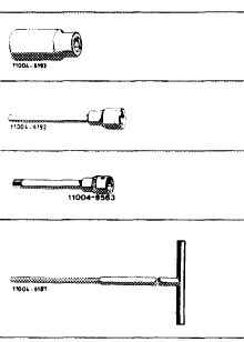 |
001 589 65 09 00
|
|||||||||||||||||||||||||||||||
|
Socket 27 mm,
1/2″ square socket for rotating engine
|
|||||||||||||||||||||||||||||||||
|
Socket 10 mm, 1/2″ square, 140 mm long for hex. socket cylinder head bolts
|
000 589 05 07 00
|
||||||||||||||||||||||||||||||||
|
Socket 1/2″ square, 140 mm long for double hex. cylinder head bolts
|
617 589 00 10 00
|
||||||||||||||||||||||||||||||||
|
Screwdriver (Allen wrench) with tommy handle for hex. socket screws, 6 mm, 440 mm long
|
116 589 03 07 00
|
||||||||||||||||||||||||||||||||
|
|
|||||||||||||||||||||||||||||||||
|
Impact puller for bearing bolt (basic unit)
|
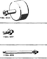 |
116 589 20 33 00
|
|||||||||||||||||||||||||||||||
|
Threaded bolt for impact puller M 6, 50 mm long
|
116 589 01 34 00
|
||||||||||||||||||||||||||||||||
|
Threaded bolt for impact puller, M 6, 150 mm long
|
116 589 02 34 00
|
||||||||||||||||||||||||||||||||
|
|
|||||||||||||||||||||||||||||||||
|
Valve adjusting wrench 14 mm (2 each)
|
 |
615 589 00 01 00
|
|||||||||||||||||||||||||||||||
|
|
|||||||||||||||||||||||||||||||||
|
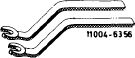
Holding wrench for valve spring retainer
|
 |
615 589 00 03 00
|
|||||||||||||||||||||||||||||||
|
|
|||||||||||||||||||||||||||||||||
|
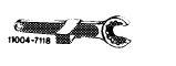
Contact handle for rotating engine (component of compression pressure recorder 001 589 46 21 00)
|
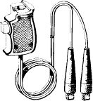 |
001 589 46 21 08
|
|||||||||||||||||||||||||||||||
|
11004-8487
|
|||||||||||||||||||||||||||||||||
|
|
|||||||||||||||||||||||||||||||||
|
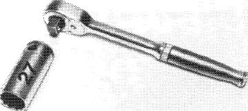
Torque wrench with plug-in ratchet, 1/2″ square, 40-200 Nrn
|
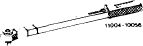 |
001 589 67 21 00
|
|||||||||||||||||||||||||||||||
|
|
|||||||||||||||||||||||||||||||||
|
02.8-415/2 F2
|
|||||||||||||||||||||||||||||||||
|
|
|||||||||||||||||||||||||||||||||
|
|
|||
|
Note
|
|||
|
|
|||
|
Remove cylinder head only from cooled-down engine. Remove together with exhaust manifold and boost air pipe.
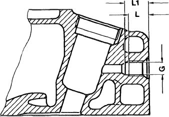
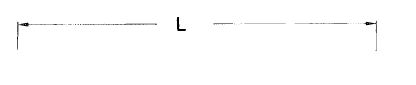
On engine 617.950 (@>starting 1980, threaded bore (G) and seat bore in cylinder head for quick-start pencil element glow plugs have been extended by 3 mm (L and L 1).
|
 |
||
|
L 19 mm L 1 22.5 mm
|
|||
|
1053-8039H
|
|||
|
|
|||
|
This cylinder head has been installed on engines 617. 951/952 from start of series.
In the event of repairs, the head can also be installed on engines 617.950 made at an earlier date. On the other hand, the cylinder head with shorter thread and seat bores should not be installed on engines with quick-start system, since a part of the quick-start effect will be lost.
|
|||
|
|
|||
|
For these engines the cylinder head gaskets require no retightening. As a result, no retightening of cylinder head bolts is required during 1st inspection (1000— 1500 km) and in the event of repair, after driving 1000-1500 km.
The cylinder head gaskets welded in-between sheeting may be removed from package only directly prior to assembly, since they are sensitive to light and ozone.
|
|||
|
|
|||
|
Removal
|
 |
||
|
1 Completely drain coolant.
|
|||
|
Drain plug on cylinder crankcase
|
|||
|
|
|||
|
01.8-415/3 F2
|
|||
|
|
|||
|
|
|||
|
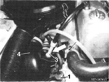
2 Remove air cleaner with intake line (4). For this purpose, pull off engine vent line (3) and on model 116.120 with double diaphragm vacuum pump, pull vacuum line (2) and cable from temperature switch (1).
|
 |
||
|
Model 116.120
1 Temperature switch 100 °C
2 Vacuum line
3 Vent line
4 Intake line
|
|||
|
|
|||
|
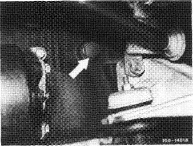
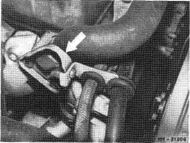
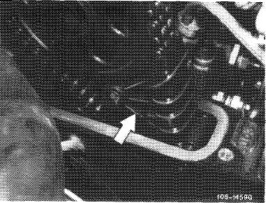
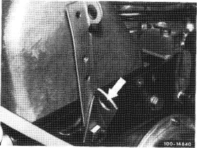
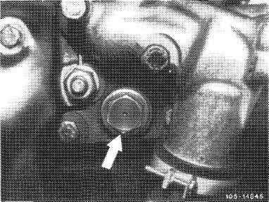
3 On engines with EGR (@)cover return line from cyclonic oil separator to oil pan (arrow).
|
 |
||
|
|
|||
|
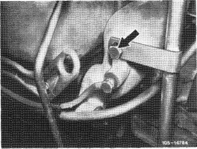
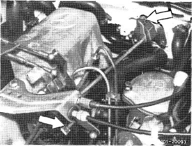
4 On model 123 with level control, unscrew line holder from thermostat housing (arrow).
|
 |
||
|
|
|||
|
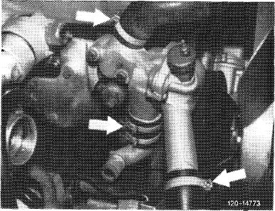
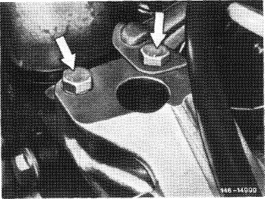
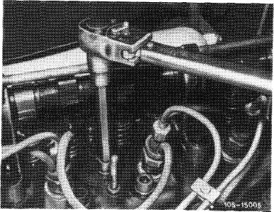
5 Disconnect the three coolant hoses (arrows) on thermostat housing and heater supply hose on cylinder head. Remove upper coolant hose to radiator.
6 Unscrew bleed line between cylinder head and water pump housing.
|
 |
||
|
|
|||
|
01.8-415/4 F2
|
|||
|
|
|||
|
|
|||
|
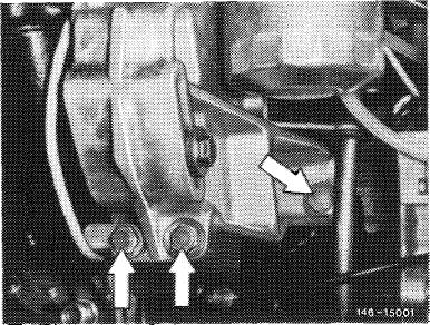
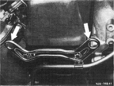
7 On model 123 with level control, remove hydraulic oil pump with connected lines and put aside.
For this purpose, unscrew screws (arrows).
|
 |
||
|
|
|||
|
8 Loosen oil filter cover and pull up for a short distance.
|
 |
||
|
|
|||
|
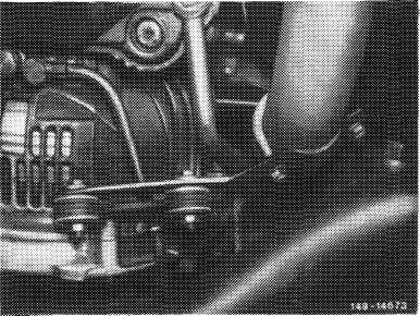
9 Unscrew exhaust on exhaust gas turbo-charger (arrow) and on transmission.
|
 |
||
|
|
|||
 |
|||
|
|
|||
|
01.8-415/5 F 2a
|
|||
|
|
|||
|
|
|||
|
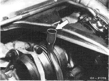
10 Unscrew oil dipstick guide tube of automatic transmission on boost air pipe.
|
 |
||
|
|
|||
|
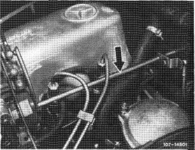
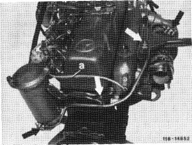
11 Completely unscrew oil feed line for exhaust gas turbo-charger.
12 Unscrew line (a) on boost air pipe.
13 Remove injection line and cover connections.
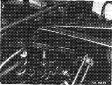
14 Unscrew or pull off cable harness on pencil element glow plugs, on pressure switch in boost air pipe and on (ui^up to 1980 on temperature switch.
|
103-14E’,,’
|
||
|
|
|||
|
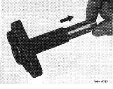
15 Pull fuel return line from 1st injection nozzle.
16 On models 123 and 126.120 with cruise control/ tempomat, unscrew actuator with holder on power steering pump carrier, disconnect linkage and put actuator aside.
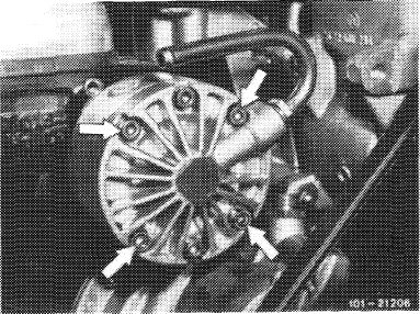
17 Remove power steering pump with bracket and fuel filter and put aside.
|
 |
||
|
|
|||
|
For this purpose, unscrew the five screws indicated by arrows.
Do not disconnect hoses and lines.
|
 |
||
|
|
|||
|
01.8-415/6 F2
|
|||
|
|
|||
|
|
|||
|
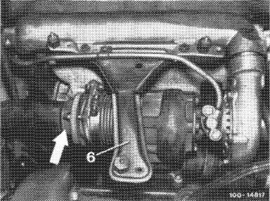
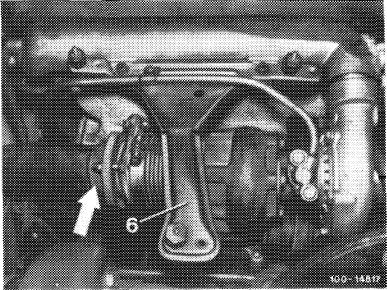
18 Remove exhaust turbo-charger.
For thislpurpose, unscrew holder (6) for air filter. Cover oil return pipe (arrow).
|
 |
||
|
|
|||
 |
|||
|
|
|||
|
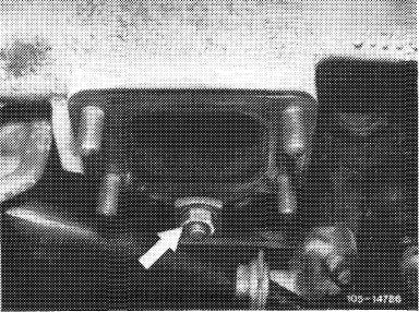
19 Unscrew exhaust manifold support on manifold (arrow).
|
 |
||
|
|
|||
|
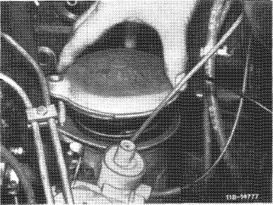
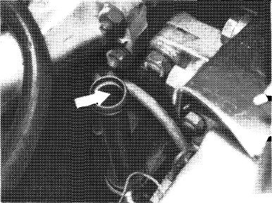
20 Remove cylinder head cover. For this purpose, disconnect regulating linkage. Pull out locking eye of longitudinal regulating shaft (arrow).
On models 116.120 and 123, pull longitudinal regulating shaft out of rubber mount in forward direction and remove in rearward direction.
|
 |
||
|
Model 116.120
|
|||
|
|
|||
|
01.8-415/7 F2
|
|||
|
|
|||
|
|
|||
|
On model 126.120, pull longitudinal regulating shaft out of guide lever in rearward direction and remove in forward direction.
|
 |
||
|
Model 123
|
|||
|
|
|||
|
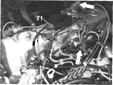
On models 123 with automatic transmission 722. 303 (W4A 040) and 126.120, pull off central plug for vacuum lines (71) or vacuum lines. Disconnect bowden wire, compress black plastic clip (arrow) and pull bowden wire out of holder in rearward direction.
|
 |
||
|
Model 126.120
|
|||
|
|
|||
|
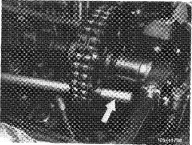
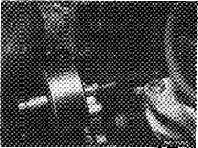
21 Loosen necked-down screw for attaching camshaft sprocket, do not screw out.
For loosening camshaft sprocket, apply counterhold with a screw driver or a steel bolt.
|
 |
||
|
|
|||
|
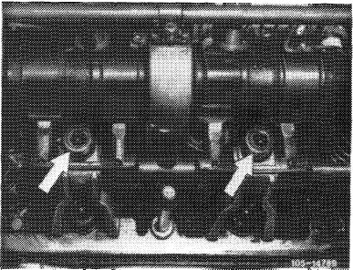
22 Remove both rocker arm groups. For this purpose, set camshaft in such a manner that the rocker arms are not under load.
|
 |
||
|
|
|||
|
01.8-415/8 F2
|
|||
|
|
|||
|
|
|||
|
23 Set engine to ignition TDC of 1st cylinder. For this purpose, rotate engine at crankshaft by means of tool combination.
|
 |
||
|
|
|||
|
24 Mark camshaft sprocket and timing chain in relation to each other.
|
 |
||
|
|
|||
|
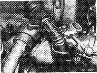
25 On engines with EGR (usa), remove pipe line between EGR valve and exhaust manifold (arrow). For this purpose, unscrew shielding plate (10).
|
 |
||
|
|
|||
|
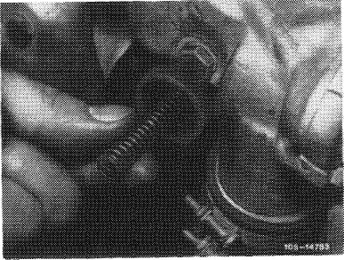
26 Unscrew closing screw of chain tensioner and remove compression spring.
|
 |
||
|
|
|||
|
01.8-415/9 F2
|
|||
|
|
|||
|
|
|||
|
27 Remove slide rail in cylinder head. Pull out bearing bolt by means of impact puller.
28 Remove camshaft sprocket.
|
 |
||
|
|
|||
 |
|||
|
|
|||
|
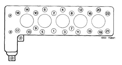
29 Loosen cylinder head bolts in reverse order of tightening diagram by means of Allen wrench insert and screw out.
Unscrew the M 8-screws by means of Allen wrench 6 mm, 440 mm long.
|
 |
||
|
|
|||
|
30 Remove injection nozzles to remove the 5 screws adjacent to injection nozzles.
|
 |
||
|
|
|||
|
01.8-415/10 F2
|
|||
|
|
|||
|
|
|||
|
31 Lift out cylinder head. This can also be done by means of a crane and an engine hoist (Motordirigent). Suspend the cables for this purpose at the three suspension eyes.
|
 |
||
|
Suspension eye front
|
|||
|
|
|||
|
Suspension eyes rear
|
 |
||
|
|
|||
|
32 Pull out thrust bolts of installed chain tensioner in inward direction (arrow).
33 Thoroughly clean cylinder crankcase and cylinder parting surface.
|
 |
||
|
|
|||
|
Installation
|
|||
|
|
|||
|
34 Mount new cylinder head gasket.
35 Mount cylinder head while paying attention to hollow dowel pins for locating cylinder head.
|
|||
|
|
|||
|
01.8-415/11 F2
|
|||
|
|
|||
|
|
|||
|
36 With double hex. cylinder head bolts, measure
|
 |
||
|
|
|||
|
43 Install slide rail.
44 Insert thrust bolts and compression spring of chain tensioner from outside.
Position closing plug with new sealing ring and tighten to 90 Nm.
|
 |
||
|
|
|||
|
45 Adjust valve clearance (05-210).
46 Install injection nozzles. Insert new nozzle reeds first.
47 Screw-on exhaust manifold support.
48 Install exhaust gas turbo-charger with new gasket. When positioning turbo-charger, pay attention to oil return pipe. Remove cover.
|
 |
||
|
|
|||
|
49 Unscrew oil feed line for exhaust gas turbo-charger. Insert new gasket for exhaust gas turbo-charger.
50 For further installation proceed vice versa to removal.
51 Add coolant (20—010) and pressure-test cooling system.
52 Bleed injection system by means of a hand pump.
53 Run engine and check for leaks.
|
|||
|
|
|||
|
Note: Retightening of cylinder head bolts and setup of valve clearance on warm engine not required.
|
|||
|
|
|||
|
|
||
 |
||
|
|
||
|
01.8-415/15 F2
|
||
|
|
||