Removal and installation of pre-chambers
|
|
||||||
|
01—417 Removal and installation of pre-chambers
|
||||||
|
|
||||||
|
Data
|
||||||
|
|
||||||
|
Pre-chamber standout on cylinder head dimension „c” 7.8—8.4 mm
|
 |
|||||
|
|
||||||
|
Tightening torques
Coupling nuts of injection lines Nuts for cylinder head cover Pre-chamber in cylinder head (threaded ring) Nozzle holder in pre-chamber
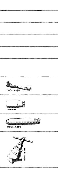
Special tools
Open box wrench insert, 17 mm, 1/2″ square socket for injection lines
Socket 27 mm, 1/2″ square socket
Socket wrench for threaded ring of pre-chamber
Puller for pre-chamber
|
 |
Nm
25
15
150-180
70-80
000 589 68 03 00
001 589 65 09 00 615 589 00 07 00
615 589 00 33 00
|
||||
|
|
||||||
|
Note
|
||||||
|
|
||||||
|
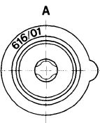
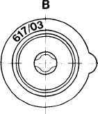
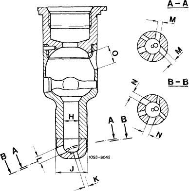
The prechambers of engines 616.912 and 617.912 may not be installed on these engines.
For identification, a code number (617/03) is shown at upper flange of pre-chamber.
In addition, the pre-chamber can be identified by means of the smaller bore (0—9 mm dia.) for glow
Plug. A Prechamber
engines 616.912/617.912
B Prechamber
engines 61 7.950/951 /952
|
 |
 |
1053-8622A2
|
|||
|
|
||||||
|
01.8-417/1 F2
|
||||||
|
|
||||||
|
|
||||||||||||||||||||||||||||||||||||||||||||||||||||||||||||||||||||||||||
|
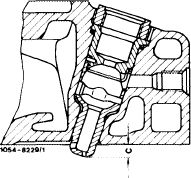
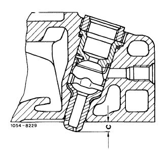
Six burner bores of different diameter are in place in pre-chamber lower half (burner neck) at different levels and angle positions.
The firing duct (H) has a diameter of 8 mm, the burner neck (J) of 16 mm.
|
 |
|||||||||||||||||||||||||||||||||||||||||||||||||||||||||||||||||||||||||
|
||||||||||||||||||||||||||||||||||||||||||||||||||||||||||||||||||||||||||
|
|
||||||||||||||||||||||||||||||||||||||||||||||||||||||||||||||||||||||||||
|
In addition, the pre-chamber bottom is of spherical shape.
The spherical shape provides uniform wall thickness in range of burner bores.
|
||||||||||||||||||||||||||||||||||||||||||||||||||||||||||||||||||||||||||
|
|
||||||||||||||||||||||||||||||||||||||||||||||||||||||||||||||||||||||||||
|
Removal
|
 |
|||||||||||||||||||||||||||||||||||||||||||||||||||||||||||||||||||||||||
|
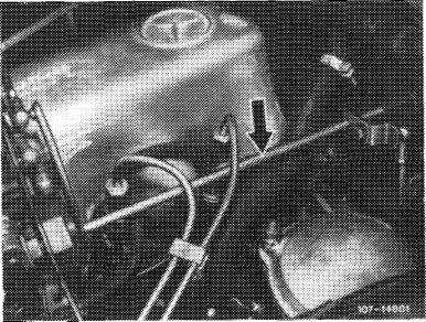
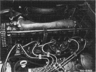
1 Disconnect regulating linkage to remove cylinder head cover. Pull out locking eye of longitudinal regulating shaft (arrow).
On models 116.120 and 123, pull longitudinal regulating shaft out of rubber mount in forward direction and remove in rearward direction.
|
||||||||||||||||||||||||||||||||||||||||||||||||||||||||||||||||||||||||||
|
Model 116.120
|
||||||||||||||||||||||||||||||||||||||||||||||||||||||||||||||||||||||||||
|
|
||||||||||||||||||||||||||||||||||||||||||||||||||||||||||||||||||||||||||
|
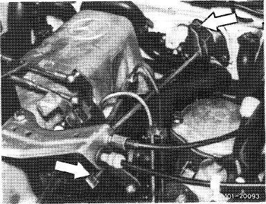
On model 126.120, pull longitudinal regulating shaft out of guide lever in rearward direction and remove in forward direction.
|
 |
|||||||||||||||||||||||||||||||||||||||||||||||||||||||||||||||||||||||||
|
Model 123
|
||||||||||||||||||||||||||||||||||||||||||||||||||||||||||||||||||||||||||
|
|
||||||||||||||||||||||||||||||||||||||||||||||||||||||||||||||||||||||||||
|
01.8—417/2 F2
|
||||||||||||||||||||||||||||||||||||||||||||||||||||||||||||||||||||||||||
|
|
||||||||||||||||||||||||||||||||||||||||||||||||||||||||||||||||||||||||||
|
|
|||
|
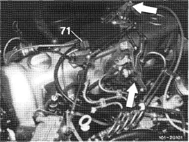
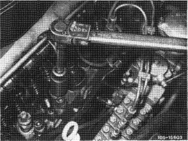
On models 123 with automatic transmission 722.303 (W4A040) and 126.120, pull off central plug for vacuum lines (71) or vacuum lines. Disconnect bowden wire, compress black plastic clip (arrow) and pull bowden wire out of holder in rearward direction.
|
 |
||
|
Model 126.120
|
|||
|
|
|||
|
2 Remove injection lines.
3 Pull fuel return hoses from injection nozzles.
|
 |
||
|
|
|||
|
4 Unscrew complete nozzle holder by means of socket (27 mm).
|
 |
||
|
|
|||
|
01.8-417/3 F2
|
|||
|
|
|||
|
|
|||
|
5 Unscrew rod-type glow plugs (81).
|
 |
||
|
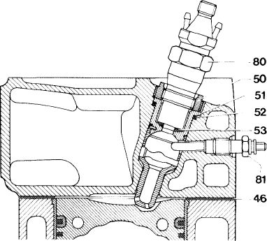
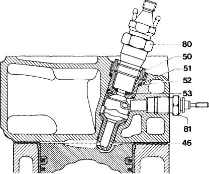
46 Cylinder head gasket
50 Threaded ring
51 Pre-chamber
52 Sealing ring
53 Nozzle reed
80 Nozzle holder
81 Rod-type glow plug
|
|||
|
|
|||
|
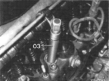
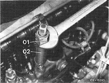
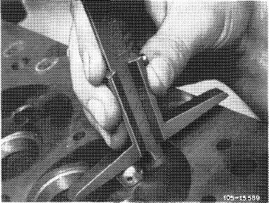
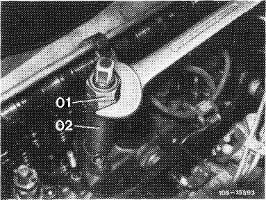
6 Unscrew threaded ring (50) by means of socket wrench.
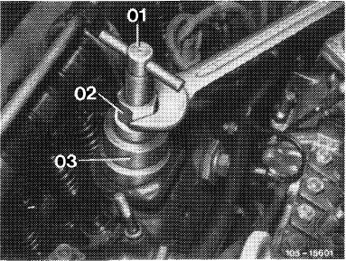
For this purpose, screw insert (03) into threaded ring, place sleeve (02) into grooves of threaded ring (arrows) and tighten with nut (01).
|
 |
||
|
03 Screw insert
|
|||
|
|
|||
|
Sleeve (02) should be seated in grooves tight enough to prevent slipping out of grooves when the threaded ring is released.
Position wrench against hex. head of sleeve (02) and unscrew threaded ring.
|
 |
||
|
01 Nut
02 Sleeve
|
|||
|
|
|||
|
01.8-417/4 F2
|
|||
|
|
|||
|
|
||||
 |
||||
|
|
||||
|
7 Pull-out pre-chamber by means of puller. Screw spindle (01) into pre-chamber. Place bell-shaped member (03) on cylinder head. The contact surface of the bell-shaped member is provided with 2 lugs. One lug each should be seated in hex. or double hex. socket of cylinder head bolt adjacent to pre-chamber. Pull-out pre-chamber by rotating nut (02) with an open-end wrench.
|
 |
|||
|
01 Spindle
02 Nut
03 Bell
|
||||
|
|
||||
|
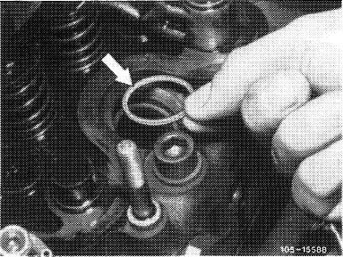
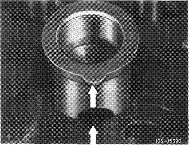
8 Remove sealing ring (arrow) from cylinder head.
|
||||
|
|
||||
|
9 Cover bore in cylinder head.
|
 |
|||
|
|
||||
|
Installation
|
||||
|
|
||||
|
Note: If the removed pre-chambers are installed again, check for perfect condition.
Ball pin should not be burnt or scaled.
In addition, if burner tops are scorched or if pre-chamber lower half shows cracks, remove boost air pipe and check inside for traces of oil.
|
||||
|
|
||||
|
01.8-417/5 F2
|
||||
|
|
||||
|
|
||||||||||||||||||||||||||||||
|
If oil-moist spots are found, check diaphragm of vacuum pump on engine 617.950 (@)up to 1979 for cracks and other damage or renew vacuum control unit on injection pump of all engines.
The faulty component is identified by means of the vacuum lines (blackened by oil).
|
||||||||||||||||||||||||||||||
|
|
||||||||||||||||||||||||||||||
|
10 Place new sealing ring (52) into cylinder head. Use original sealing ring of specified thickness and shape only, so that the required distance (c) of 7.8—8.4 mm between pre-chamber and cylinder head is maintained.
Note: If a cylinder head has been faced at parting surface, add thicker sealing rings (52) between cylinder head and pre-chamber when installing pre-chambers.
|
 |
|||||||||||||||||||||||||||||
|
|
||||||||||||||||||||||||||||||
|
The following sealing rings are available:
|
 |
|||||||||||||||||||||||||||||
|
||||||||||||||||||||||||||||||
|
|
||||||||||||||||||||||||||||||
|
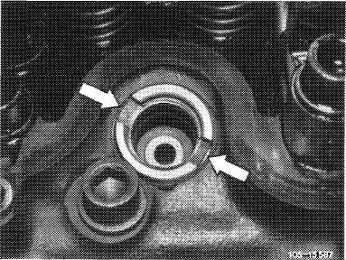
11 Screw spindle (01) of puller into pre-chamber (illustration item 7). Position pre-chamber in such a manner that the lug faces recess in cylinder head (arrows).
Insert pre-chamber by means of light blows with a plastic hammer against spindle. Pull bell-shaped member (03) with one hand in upward direction and hold in place (illustration item 7).
|
 |
|||||||||||||||||||||||||||||
|
|
||||||||||||||||||||||||||||||
|
01.8-417/6 F2
|
||||||||||||||||||||||||||||||
|
|
||||||||||||||||||||||||||||||
|
|
|||
|
12 Lubricate threaded ring (50) and tighten to specified torque of 150—180 Nm by means of pertinent socket wrench.
13 Screw-in pencil element glow plugs and connect.
14 Insert new nozzle plate (53 Fig. item 5). The resilient nozzle plate can be installed on all engines.
|
 |
||
|
53 Nozzle plate
80 Nozzle holder
81 Pencil element glow plug
|
|||
|
|
|||
|
1073-8020/1
|
|||
|
|
|||
|
15 Completely screw-in nozzle holder and tighten to 70-80 Nm.
16 Install injection lines.
17 Plug fuel return hoses to injection nozzles.
18 Mount cylinder head cover.
|
 |
||
|
|
|||
|
01.8-417/7 F2
|
|||
|
|
|||