Removal and installation of throttle valve housing
|
|
|||||
|
07.3—230 Removal and installation of throttle valve housing
|
|||||
|
|
|||||
|
Note
|
|||||
|
|
|||||
|
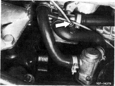
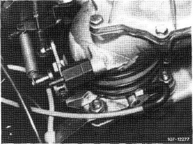
Connection (arrow) for ignition retard on throttle valve housing is no longer installed.
|
|||||
|
|
|||||
 |
1074-938811
 |
||||
|
|
|||||
|
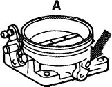
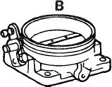
A Former version B Present version
|
|||||
|
|
|||||
|
To obtain a higher speed following a cold start at low outside temperatures, the connection on throttle valve housing for ignition retard has been transferred from throttle valve housing to contour hose between auxiliary air valve and idle speed air distributor starting April 1978. In-between, the connection on throttle valve housing has been closed by means of a rubber cap.
|
 |
||||
|
|
|||||
|
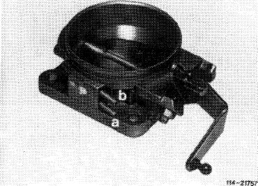
Starting September 1981, the throttle valve housing is provided with 2 connections.
Connection „a” for EGR (function diagram refer to 14-500).
Connection „b”for ignition advance.
|
 |
||||
|
|
|||||
|
07.3.2 Ma—230/1
|
F 2
|
||||
|
|
|||||
|
|
|||
|
Removal
|
|||
|
|
|||
|
1 Remove mixture controller with air guide housing (07.3-225).
2 Loosen and remove rubber sleeve.
|
|||
|
|
|||
|
3 Disconnect regulating linkage and return spring.
4 Pull off vacuum connections.
5 Loosen fastening nuts and remove throttle valve housing.
|
 |
||
|
|
|||
|
Installation
|
|||
|
|
|||
|
6 For installation proceed vice versa, using new gasket.
7 Adjust regulating linkage (30-300).
8 Adjust idle speed (07.3-100).
|
|||
|
|
|||
|
07.3.2 I la-230/2 F2
|
|||
|
|
|||