Disassembly, cleaning, assembly and adjustment of injection nozzles
|
|
||||||||||||||||||||||||||||||||||
|
07.1—137 Disassembly, cleaning, assembly and adjustment of injection nozzles
Job no. of flat rates or standard texts and flat rates data 07-6750 or 6752.
|
||||||||||||||||||||||||||||||||||
|
|
||||||||||||||||||||||||||||||||||
|
||||||||||||||||||||||||||||||||||
|
|
||||||||||||||||||||||||||||||||||
|
DNOSD 240/3)
|
||||||||||||||||||||||||||||||||||
|
|
||||||||||||||||||||||||||||||||||
|
2> The difference between any two injection nozzles within one engine must not exceed 5 bar positive. ) Starting production code no. 928 or 041.. ) Starting November 1981 with center hole 0.20 mm dia. (formerly 0.15 mm dia.)
|
||||||||||||||||||||||||||||||||||
|
|
||||||||||||||||||||||||||||||||||
|
||||||||||||||||||||||||||||||||||
|
|
||||||||||||||||||||||||||||||||||
|
Cleaner
|
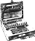 |
000 589 00 68 00
|
||||||||||||||||||||||||||||||||
|
|
||||||||||||||||||||||||||||||||||
|
Conventional tools
|
||||||||||||||||||||||||||||||||||
|
|
||||||||||||||||||||||||||||||||||
|
Torque wrench 1/2″ drive, 40-130 Nm
|
||||||||||||||||||||||||||||||||||
|
|
||||||||||||||||||||||||||||||||||
|
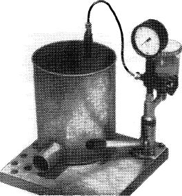
Tester EFEP 60 H
|
e.g. Bosch, D-7000 Stuttgart, Order No.
 |
|||||||||||||||||||||||||||||||||
|
|
||||||||||||||||||||||||||||||||||
|
Cleaning needles 0.13 mm dia.
|
e.g. Bosch, D-7000 Stuttgart, Order No. KDEP 2900/3
|
|||||||||||||||||||||||||||||||||
|
|
||||||||||||||||||||||||||||||||||
|
Cleaning needles 0.18 mm dia.
|
e.g. Bosch, D-7000 Stuttgart Order No. KDEP 2900/5
|
|||||||||||||||||||||||||||||||||
|
|
||||||||||||||||||||||||||||||||||
|
07.1.8-137/1 F3
|
||||||||||||||||||||||||||||||||||
|
|
||||||||||||||||||||||||||||||||||
|
|
|||
|
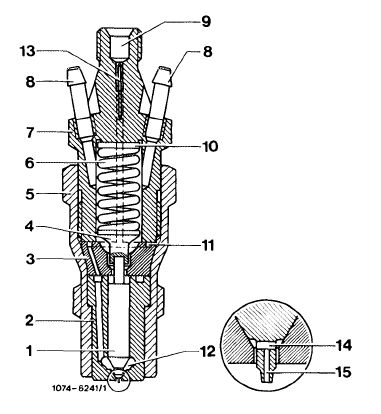
Note
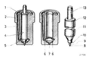
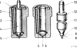
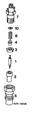
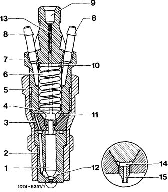
The engine is equipped with a center hole pintle nozzle which is distinguished from the standard pintle by a cross hole and a center hole (14 and 15) in the thrust pin. Moreover, a maintenance-free edge filter (13) is pressed into upper part (7) of the injection nozzle holder.
|
|||
|
|
|||
|
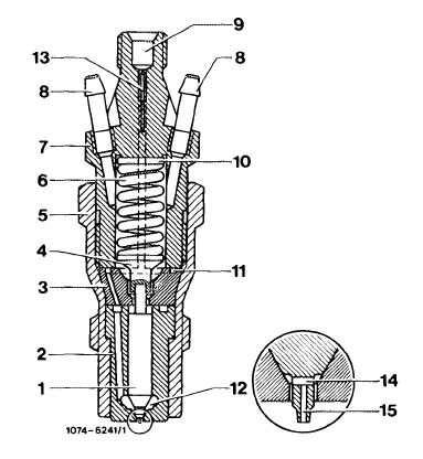
1 Needle valve
2 Nozzle body
3 Nozzle holder insert
4 Thrust pin
5 Injection nozzle holder, lower part
6 Compression spring
7 Injection nozzle holder, upper part
8 Leak-off connection
9 Fuel inlet
10 Steel shim
11 Annular groove and inlet ports
12 Pressure chamber in nozzle body
13 Edge filter
14 Cross hole
1 5 Center hole
|
 |
||
|
|
|||
|
Disassembly
|
|||
|
|
|||
|
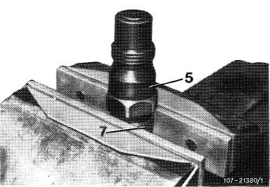
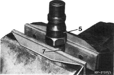
1 Clamp upper part (7) of injection holder in vise so that leak-off connections cannot be damaged.
2 Using socket, release and unscrew lower part (5) of injection nozzle holder.
|
 |
||
|
5 Injection nozzle holder, lower part 7 Injection nozzle holder, upper part
|
|||
|
|
|||
|
3 Remove steel shim (10), compression spring (6), thrust pin (4), nozzle holder insert (3) and nozzle body (2) together with needle valve (1).
Attention:
When disassembling nozzle, be sure to keep nozzle body, needle valve and all other parts in correct order.
|
|||
|
|
|||
|
07.1.8-137/2 F3
|
|||
|
|
|||
|
|
||||||||||||||||||||||||||||||||||||||||||||||||||||||||||||||||||||||||||
|
Cleaning
|
||||||||||||||||||||||||||||||||||||||||||||||||||||||||||||||||||||||||||
|
|
||||||||||||||||||||||||||||||||||||||||||||||||||||||||||||||||||||||||||
|
4 Using brass brush, remove carbon deposits from end face of nozzle body (2), chiefly around nozzle orifice.
Using surface plate, check nozzle holder insert (3) and nozzle body (2) for truth at both ends.
|
 |
|||||||||||||||||||||||||||||||||||||||||||||||||||||||||||||||||||||||||
|
||||||||||||||||||||||||||||||||||||||||||||||||||||||||||||||||||||||||||
|
|
||||||||||||||||||||||||||||||||||||||||||||||||||||||||||||||||||||||||||
|
5 Clean pressure chamber (5) in nozzle body using annular groove scraper.
|
 |
|||||||||||||||||||||||||||||||||||||||||||||||||||||||||||||||||||||||||
|
||||||||||||||||||||||||||||||||||||||||||||||||||||||||||||||||||||||||||
|
|
||||||||||||||||||||||||||||||||||||||||||||||||||||||||||||||||||||||||||
|
6 Clean nozzle needle seat in nozzle body with cleaning cutter. This job should be given special care, since usability of a nozzle depends to a high degree on a good nozzle needle seat.
Do not apply excessive pressure with cleaning cutter.
Clean center hole (15 in fig. item 4) with cleaning needle (0.13 mm dia. or 0.18 mm dia.).
|
||||||||||||||||||||||||||||||||||||||||||||||||||||||||||||||||||||||||||
|
|
||||||||||||||||||||||||||||||||||||||||||||||||||||||||||||||||||||||||||
|
07.1.8-137/3 F3
|
||||||||||||||||||||||||||||||||||||||||||||||||||||||||||||||||||||||||||
|
|
||||||||||||||||||||||||||||||||||||||||||||||||||||||||||||||||||||||||||
|
|
|||||||||||||||||||||||||||||||||||||||||||||||||||||||||
|
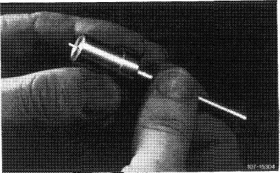
7 Clean injection hole in nozzle orifice, using injection hole cleaner. As can be seen in the illustration, work from inside to outside and not vice versa (so that injection hole cleaner is guided correctly and not twisted).
|
 |
||||||||||||||||||||||||||||||||||||||||||||||||||||||||
|
|
|||||||||||||||||||||||||||||||||||||||||||||||||||||||||
|
8 Clean nozzle needle with brass brush.
|
|||||||||||||||||||||||||||||||||||||||||||||||||||||||||
|
|
|||||||||||||||||||||||||||||||||||||||||||||||||||||||||
|
 |
||||||||||||||||||||||||||||||||||||||||||||||||||||||||
|
|
|||||||||||||||||||||||||||||||||||||||||||||||||||||||||
|
Checking the needle valve
|
|||||||||||||||||||||||||||||||||||||||||||||||||||||||||
|
|
|||||||||||||||||||||||||||||||||||||||||||||||||||||||||
|
9 Subject to sight-check. Used nozzles are to be sight-checked after cleaning. Check needle valve for indented or rough seat, and also for worn or damaged injection pins. Exchange any nozzle that is damaged.
|
|||||||||||||||||||||||||||||||||||||||||||||||||||||||||
|
|
|||||||||||||||||||||||||||||||||||||||||||||||||||||||||
|
07.1.8-137/4 F3
|
|||||||||||||||||||||||||||||||||||||||||||||||||||||||||
|
|
|||||||||||||||||||||||||||||||||||||||||||||||||||||||||
|
|
|||
|
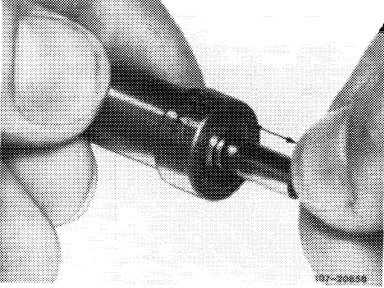
10 Carry out test for freedom of movement. To do so, immerse needle valve and nozzle body in filtered diesel fuel, inserting needle valve into nozzle body. Hold nozzle body vertically and draw needle valve out by about one third. It must be able to slide back into its seat under its own weight. Exchange injection nozzle if necessary.
|
 |
||
|
|
|||
|
Assembly
|
 |
||
|
11 Introduce all parts into lower part (5) of injection nozzle in reverse order and screw on upper part (7). Be sure to fit thrust pin (4) on needle valve (1) at end showing hole.
|
|||
|
|
|||
|
12 Clamp upper part (7) of injection nozzle in vise and torque lower part (5) to 70-80 Nm.
|
|||
|
|
|||
 |
|||
|
|
|||
|
07.1.8-137/5 F3
|
|||
|
|
|||
|
|
||||
|
Checking
13 Check injection nozzles for satisfactory jet, rattling sound, injection pressure and leakage (07.1-135).
|
 |
107-20857
|
||
|
|
||||
|
Adjustment
|
 |
|||
|
14 In order to obtain correct injection pressure setting, it may be necessary to insert or remove steel shims (10) between compression spring (6) and upper part (7) of injection nozzle.
Inserting = higher injection pressure
Removing = lower injection pressure
These shims are available in thicknesses of 1.0 to 1.8 mm, in steps of 0.05 to 0.05 mm. Increasing the preloading by 0.05 mm increases the injection pressure by about 3.0 bar positive.
|
||||
|
|
||||
|
07.1.8-137/6 F3
|
||||
|
|
||||