Operation
|
|
||
|
14-050 Operation
|
||
|
|
||
|
Federal and California version model year 1977/78/79 A. General
|
||
|
|
||
|
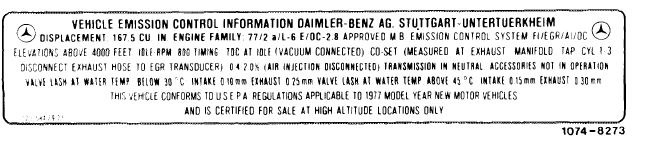
Information plate
|
||
|
|
||
|
Federal version basic color black California version basic color yellow Federal version high altitudes basic color red
|
||
|
|
||
 |
||
|
|
||
|
Identification of vacuum lines
|
||
|
|
||
|
The basic color of vacuum lines for emission control Lines originating at a vacuum source (originating
system is transparent (white). lines) have only one color stripe.
Additional color stripes are used to facilitate identifi- Lines terminating at a vacuum-operated device (termi-
cation of the individual functions. nating lines) have two color stripes. Purple is always
the second color.
Emission control system Color coding of Color coding of
originating vacuum line terminating vacuum line
Ignition
Advance red —
Retard yellow yellow/purple
EGR red –
Air injection blue blue/purple
|
||
|
|
||
|
Engine 110 is available with two different emission The two emission control systems differ with regard
control systems: to air injection and catalysts.
1. Federal emission control system (black information plate).
2. California emission control system (yellow information plate).
|
||
|
|
||
|
14.2-050/1 USA 1977/78/79 F2
|
||
|
|
||
|
|
||||
|
B. EGR
|
||||
|
|
||||
|
To reduce nitrogen oxides in exhaust gases, a portion of the gases from the exhaust manifold is returned to the intake pipe through a valve.
The quantity of the returned exhaust gas is limited and cut off completely in some driving conditions, so that the driving characteristics of the vehicle are not influenced.
|
||||
|
|
||||
|
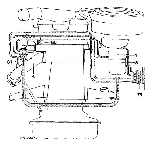
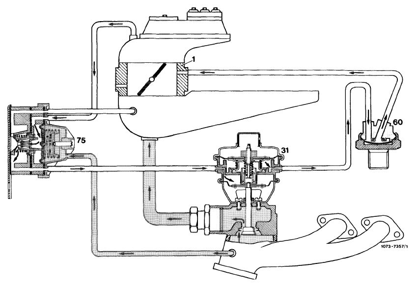
Function diagram
|
 |
|||
|
1 Throttle valve housing
3 Intake pipe
4 Exhaust manifold 31 EGR valve
60 Thermo valve 40 °C
75 Pressure transducer
|
||||
|
|
||||
|
Components of EGR:
|
||||
|
|
||||
|
EGR valve
The EGR valve is designed as a three-diaphragm valve for better adaptation of EGR.
|
 |
|||
|
|
||||
|
14.2-050/2 USA 1977/78/79 F2
|
||||
|
|
||||
|
|
||||
|
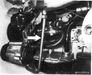
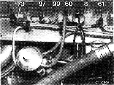
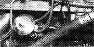
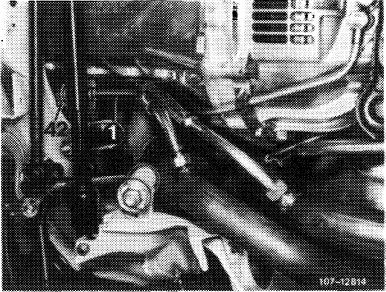
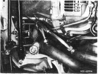
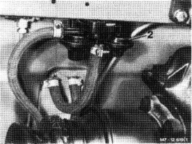
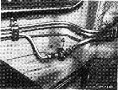
EGR line
The exhaust gases are guided by the EGR valve at the front around the engine through the EGR line (arrow) into intake pipe.
|
 |
|||
|
|
||||
|
Pressure transducer
The pressure transducer controls the EGR volume in dependence of the exhaust backpressure.
|
 |
|||
|
|
||||
|
107-12314
|
||||
|
|
||||
|
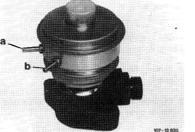
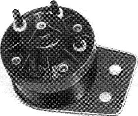
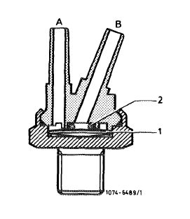
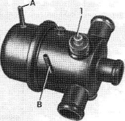
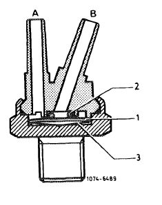
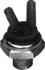
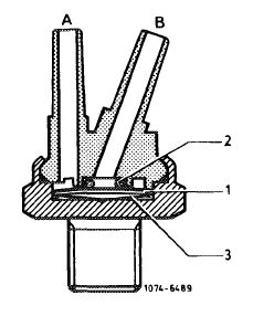
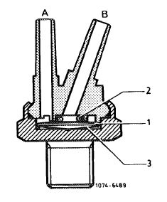
Thermovalve 40 °C (color code black)
The thermovalve is screwed into sensor box and opens at approx. 40 °C coolant temperature.
|
 |
|||
|
1 Bimetallic plate
2 O-ring
A To EGR valve
B To throttle valve housing
|
||||
|
|
||||
|
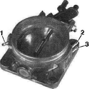
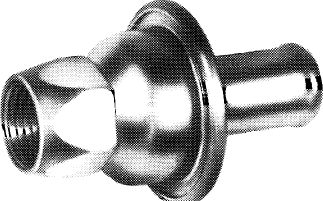
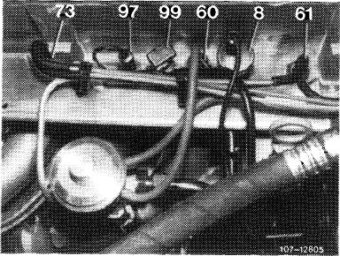
Throttle valve housing
A tapping pipe (2) is attached to throttle valve housing to draw the vacuum required for controlling the EGR and the vacuum advance of the firing point.
|
 |
107-13053
|
||
|
1 Vacuum connection ignition retard
2 Vacuum connection ignition advance
3 Vacuum connection charcoal canister
|
||||
|
|
||||
|
14.2-050/3 USA 1977/78/79 F2
|
||||
|
|
||||
|
|
|||
|
EGR is activated:
|
|||
|
|
|||
|
• above 40 °C coolant temperature.
• during acceleration.
• during partial load operation.
• during transition to deceleration (coasting).
|
|||
|
|
|||
|
Operation
|
 |
||
|
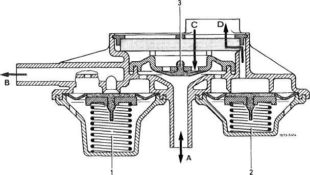
Above 40 °C, in the driving ranges named above, a part of the exhaust gases is returned from the exhaust manifold to the intake pipe.
The amount of recirculated exhaust gases depends on the throttle valve position (vacuum tapped at throttle valve housing) and the exhaust backpressure in exhaust manifold. Depending on throttle valve position the center diaphragm chamber of the EGR valve is more or less supplied with vacuum via thermovalve 40 °C (60) in cylinder head.
The upper diaphragm chamber is continuously connected to atmosphere by means of a vent bore.
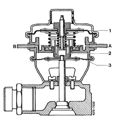
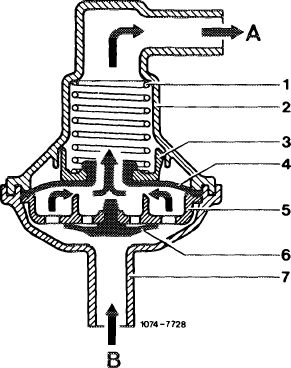
Depending on vacuum, the shut-off diaphragm (1) is pushed with coupling pin downwards against spring force and the valve can open.
Opening and closing of valve is controlled by pressure transducer which provides the positive or negative ventilation for diaphragm chamber above working diaphragm (3) depending on pressure of exhaust gases in exhaust manifold.
|
|||
|
|
|||
|
1 Shut-off diaphragm
2 Cup-type diaphragm
3 Working diaphragm
A Connection vacuum line to thermo valve
B Connection vacuum line from pressure transducer
|
 |
||
|
|
|||
|
14.2-050/4 USA 1977/78/79 F2
|
|||
|
|
|||
|
|
|||
|
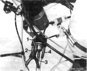
The pressure transducer is subdivided into three chambers by means of two spring-loaded diaphragms, the upper diaphragm (1) and the lower diaphragm (2). Both diaphragms are connected to each other by means of a diaphragm cup.
|
 |
||
|
1 Connection intake pipe vacuum (blue)
2 Connection vent line (white)
3 Connection exhaust gas backpressure line (orange)
4 Connection vacuum control line to EGR valve (brown)
|
|||
|
|
|||
|
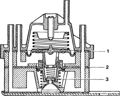
The exhaust gas backpressure is effective in upper diaphragm chamber. The center diaphragm chamber is continuously and positively vented through air guide housing. This will not influence the position of the diaphragms. The lower diaphragm chamber is positively or negatively vented depending on exhaust gas backpressure.
|
 |
||
|
1 Upper diaphragm
2 Lower diaphragm
3 Diaphragm cup
|
|||
|
1074-7346/1
|
|||
|
|
|||
|
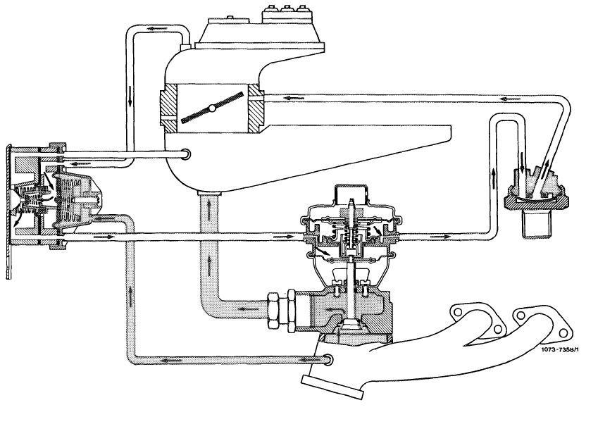
Function diagram EGR valve opened
|
|||
|
|
|||
 |
|||
|
|
|||
|
14.2-050/5 USA 1977/78/79 F2
|
|||
|
|
|||
|
|
||
|
The different driving conditions provide three positions for pressure transducer:
1. During acceleration the exhaust gas backpressure increases and forces the upper diaphragm with diaphragm cup and the lower diaphragm in downward direction.
The valve plate in diaphragm cup closes the intake pipe vacuum line in lower diaphragm chamber. Simultaneously, the valve plate opens the positive venting bore from center to lower diaphragm chamber. The lower diaphragm in EGR valve is positively vented by means of the vacuum control line coming from lower diaphragm schamber. The spring in EGR valve pushes the working diaphragm with valve down. The valve opens completely and the largest possible quantity of exhaust gases flows to intake pipe.
2. During transition to deceleration (coasting) the exhaust gas backpressure decreases. The upper diaphragm (1) including the diaphragm cup and the lower diaphragm are returning to their starting position. The valve plate opens the intake pipe vacuum line and seats on lower part of diaphragm cup. This will interrupt the positive venting of the lower diaphragm chamber. The intake pipe vacuum now prevailing in this diaphragm chamber provides the negative ventilation for the lower diaphragm in EGR valve via the vacuum control line. Depending on size of vacuum the valve is pulled in closing direction against the spring force. The quantity of fed exhaust gas increases.
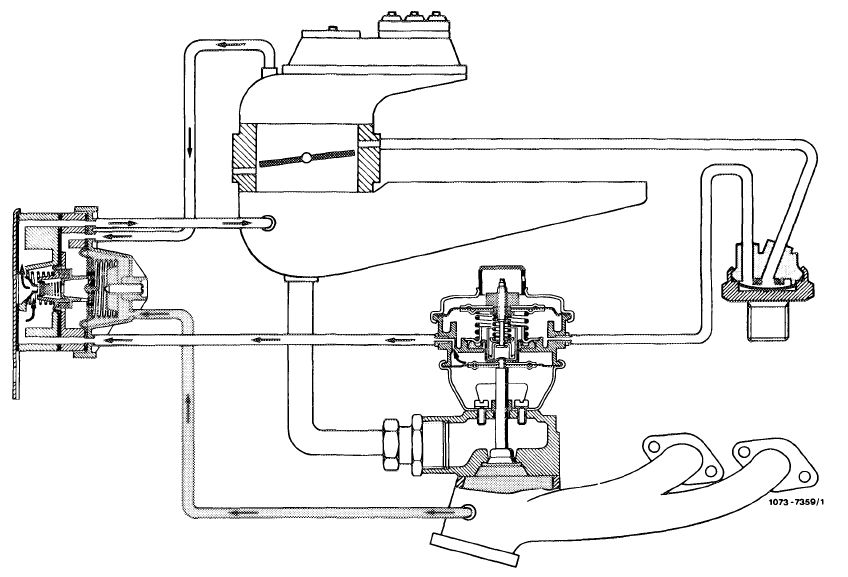
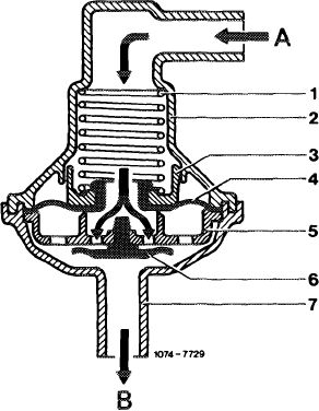
Function diagram EGR valve in center position
|
||
|
|
||
 |
||
|
|
||
|
14.2-050/6 USA 1977/78/79 F2
|
||
|
|
||
|
|
||
|
3. During constant driving the pressure conditions in upper and lower diaphragm chamber are in balance. The EGR valve remains in its momentary position. The recirculated quantity of exhaust gases remains constant.
|
||
|
|
||
|
Function diagram EGR valve closed
|
||
|
|
||
 |
||
|
|
||
|
In this case, the upper diaphragm chamber in EGR valve is not provided with a vacuum and the shut-off diaphragm is not releasing the required valve stroke.
|
||
|
|
||
|
C. Air injection Federal version
|
||
|
|
||
|
To reduce the incompletely burnt components in the exhaust gases, air is injected into hot zone behind exhaust valves.
Afterburning is controlled by way of the engine temperature and pressure conditions in intake pipe.
|
||
|
|
||
|
14.2-050/7 USA 1977/78/79 F2
|
||
|
|
||
|
|
|||
|
To avoid backfiring in exhaust, as well as overheating of catalyst, the air injection is shut off in given driving ranges.
|
|||
|
|
|||
 |
|||
|
|
|||
|
Components of air injection:
|
|||
|
|
|||
|
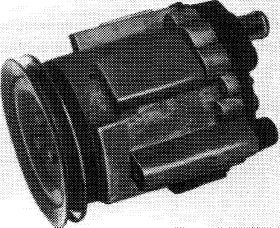
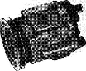
Air pump (Saginaw pump)
The air pump is an impeller pump with maintenance-free centrifugal filter which cleans the drawn-in air.
|
 |
||
|
|
|||
|
14.2-050/8 USA 1977/78/79 F2
|
|||
|
|
|||
|
|
|||
|
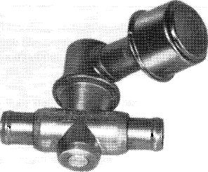
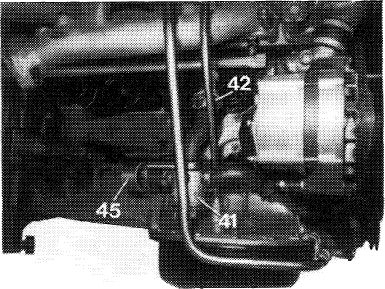
Anti-backfire valve
The anti-backfire valve serves the purpose of controlling the air volume in dependence of operating condition of engine.
Since there is no safety valve on air pump, the safety valve (1) is attached to anti-backfire valve.
|
 |
||
|
|
|||
|
107-10004
|
|||
|
|
|||
|
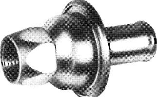
Check valve
The check valve prevents hot exhaust gases from flowing into air line.
|
 |
||
|
|
|||
|
107-9193
|
|||
|
|
|||
|
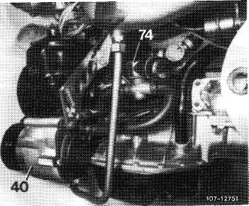
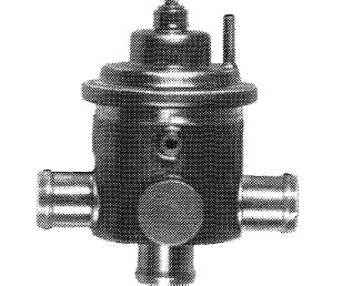
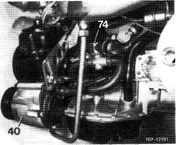
Pressure relief valve
The excess air delivered by the air pump at high engine speeds is discharged into the open air by the pressure relief valve starting at a line backpressure of approx. 0.266 bar gauge pressure. An air filter is attached to pressure relief valve for silencing.
|
 |
||
|
|
|||
|
–13007
|
|||
|
|
|||
|
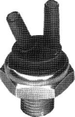
Thermo valve 17 °C (color code blue)
The thermovalve is screwed into cylinder head and opens at approx. 17 °C coolant temperature. Below 17 °C coolant temperature the bimetallic plate rests against O-ring and closes connection „B”.
Above 17 °C coolant temperature the bimetallic plate snaps downward when heated. Both connections are connected to each other.
|
 |
||
|
|
|||
|
I07-108V5
|
|||
|
|
|||
|
14.2-050/9 USA 1977/78/79 F2
|
|||
|
|
|||
|
|
|||
|
The vacuum line to intake pipe should be plugged to connection „B”, since this is the only way to guarantee the absolute absence of leaks between bimetallic plate and O-ring.
|
 |
||
|
1 Bimetallic plate
2 O-ring
|
|||
|
|
|||
|
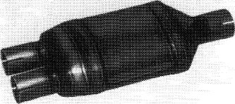
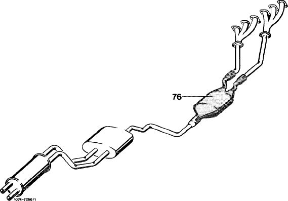
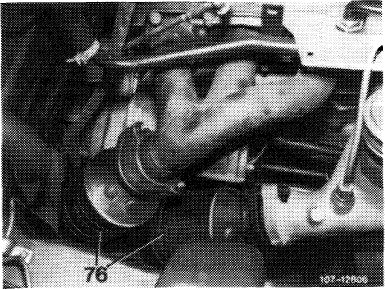
Catalyst
The catalyst is designed as an underf loor catalyst and is located in exhaust system in front of mufflers.
|
 |
||
|
|
|||
|
Operation
|
 |
||
|
Starting at a coolant temperature of approx. 17 °C in cylinder head air is discharged into exhaust ducts of cylinder head at idle speed, during deceleration and under partial load.
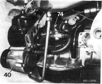
The air pump is driven by the crankshaft via a V-belt and delivers constantly air when the engine in running. The air flows to pressure relief valve (74) which discharges the excess air delivered at high speeds into the open air starting at a back-pressure of approx. 0.266 bar.
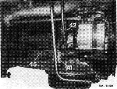
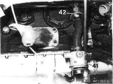
From pressure relief valve (74) the excess air is diverted into the exhaust ducts of the cylinder head via the di-verter valve (41), and starting at approx. 17 °C coolant temperature via the check valve (42), while below approx. 17 °C coolant temperature the excess air is discharged into the open air through the air filter for silencing (45).
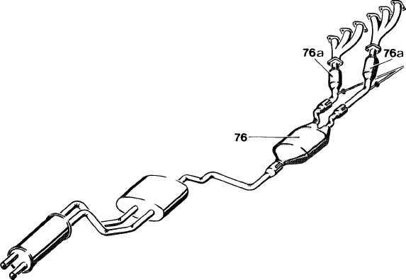
The exhaust gases and the diverted air are routed through exhaust pipes into catalyst (76).
The oxygen in the diverted (injected) air encounters the hot exhaust gases for reaction in catalyst.
|
|||
 |
|||
|
|
|||
|
14.2-050/10 USA 1977/78/79 F2
|
|||
|
|
|||
|
|
||
|
The catalyst comprises an oval monolith elastically supported in a wire netting, a honeycomb-shaped cylindrical body of ceramic material. The noble metal evaporated on the monolith, the actual catalyst, accelerates the oxidation of CO and hydrocarbons while adding fresh air at the proper temperature.
 |
||
|
|
||
|
To maintain function of catalyst, the engine should be operated with lead-free fuel only.
|
||
|
|
||
|
Avoid overheating of catalyst
Extended overheating of the catalyst will result in catalyst damage, i.e. the monoliths in catalyst may melt.
Overheating of catalyst may occur if:
a) The specified engine service is not performed.
Perfect spark plugs are important for life of catalyst.
b) The fuel air mixture is excessively enriched by irregular operation of engine.
c) The exhaust emission control system has been arbitrarily modified.
|
||
|
|
||
|
14.2-050/11 USA 1977/78/79 F2
|
||
|
|
||
|
|
|||
|
D. Air injection California version
|
|||
|
|
|||
|
To reduce the incompletely burnt components in exhaust gas, air is injected into hot zone behind exhaust valves.
Afterburning is controlled by means of the engine temperature and vacuum conditions in intake pipe.
To prevent backfiring in exhaust, as well as overheating of reactor, the air injection is switched off in given driving ranges.
|
|||
|
|
|||
|
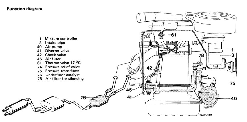
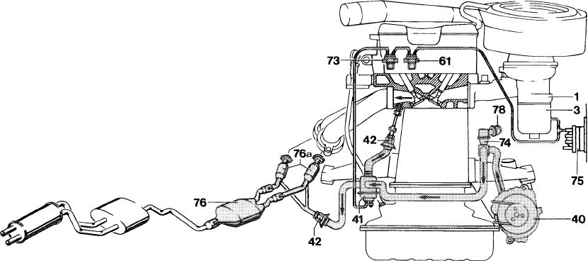
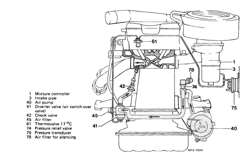
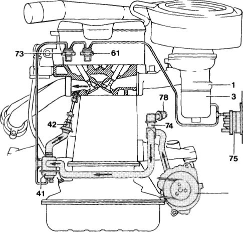
Function diagram
|
|||
|
|
|||
|
Mixture controller Intake pipe Air pump Diverter valve Check valve Thermovalve 17 °C Thermovalve 50 °C Pressure relief valve Pressure transducer Underfloor catalyst
1
3
40 41 42 61 73 74 75 76
76a Catalysts 78 Air filter for silencing
|
|||
|
1073-7470
|
|||
|
|
|||
|
Components of air injection:
|
|||
|
|
|||
|
Air pump (Saginaw pump)
The air pump is an impeller pump with maintenance-free centrifugal filter which cleans the drawn-in air.
|
 |
||
|
|
|||
|
107-8959/1
|
|||
|
|
|||
|
14.2-050/12 USA 1977/78/79 F2
|
|||
|
|
|||
|
|
|||
|
Air switch-over valve (diverter valve)
Design and function of air switch-over valve (41) corresponds to the already known diverter valve with vent, except that this valve is used here to switch over the air injection.
|
 |
||
|
|
|||
|
107-9139
|
|||
|
|
|||
|
Check valve
|
|||
|
|
|||
|
The check valve prevents hot exhaust gases from flowing into air line.
|
 |
||
|
|
|||
|
107-9193
|
|||
|
|
|||
|
Pressure relief valve
The excess air delivered by the air pump at high engine speeds is discharged into the open air by the pressure relief valve starting at a line backpressure of approx. 0.266 bar gauge pressure. An air filter is attached to pressure relief valve for silencing.
|
 |
||
|
|
|||
|
mr-13007
|
|||
|
|
|||
|
Thermo valve 17 °C (color code blue)
The thermovalve (61) is screwed into cylinder head (sensor box) and opens at approx. 17 °C coolant temperature. Below 17 °C coolant temperature the bimetallic plate rests against O-ring and closes connection „B”.
Above 17 °C coolant temperature the bimetallic plate snaps downward when heated. Both connections are connected to each other.
|
 |
||
|
|
|||
|
107-10895
|
|||
|
|
|||
|
14.2-050/13 USA 1977/78/79 F2
|
|||
|
|
|||
|
|
|||
|
The vacuum line to intake pipe should be plugged to connection „B”, since this is the only way to guarantee the absolute absence of leaks between bimetallic plate and O-ring.
|
 |
||
|
1 Bimetallic plate
2 O-ring
A Vacuum terminating line
B Vacuum originating line
|
|||
|
|
|||
|
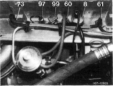
Thermovalve 50 °C (color code black with green dot)
|
|||
|
|
|||
|
The thermovalve (73) is also screwed into cylinder and closes at a coolant temperature of approx. 50 °C.
Below 50 °C coolant temperature the vacuum from prior thermovalve 17 °C (61) can act directly on diverter valve (41) via thermo valve 50 °C (73).
Above approx. 50 °C coolant temperature the bimetallic plate snaps over under influence of heat and the connection to thermovalve 17 °C (61) is closed.
The vacuum hose of thermovalve 17 °C (61) should always be plugged to diagonal connection (B) since this alone guarantees absolute protection against leaks when valve is closed.
Note: Color code starting model year 1978 is green, designation „50 AC 13”.
|
 |
||
 |
|||
|
|
|||
|
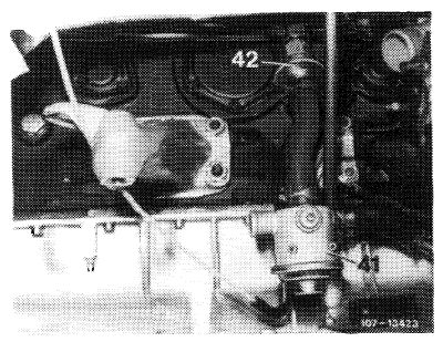
Air injection line
An air line (1) is installed on engine for air injection between catalysts.
|
 |
||
|
|
|||
|
14.2-050/14 USA 1977/78/79 F2
|
|||
|
|
|||
|
|
|||
|
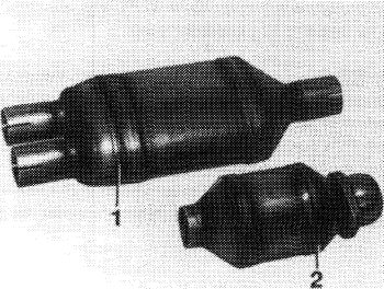
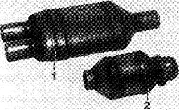
Catalysts
Three catalysts are installed in exhaust system in front of mufflers (silencers).
One small catalyst (2) each for three cylinders is mounted directly on exhaust manifold and one underfloor catalyst (1) for all six cylinders under vehicle floor.
|
 |
||
|
|
|||
|
Operation
|
 |
||
|
The air pump (40) is driven by the crankshaft via a V-belt and delivers constantly air when the engine is running. The air flows to pressure relief valve (74) which discharges the excess air delivered at high speeds into the open air starting at a backpressure of approx. 0.266 bar.
From pressure relief valve (74) the excess air is diverted into the exhaust ducts of the cylinder head via the air switch-over valve (41) or behind the small catalysts into the exhaust pipes.
The air switch-over by means of the air switch-over valve is controlled by thermovalves 17 °C (61) and 50°C(73).
There are three temperature ranges:
|
|||
 |
|||
|
1. Coolant temperature below 17 °C (air injection behind small catalysts in exhaust pipes)
The thermovalve 17 °C (61) is closed, the thermo-valve 50 °C (73) is open. No vacuum flows to diaphragms of air switch-over valve (41), the diaphragm is positively vented by the vent cap on valve. The compression spring in air switch-over valve closes the injection line to cylinder head. The delivered air is injected into exhaust pipes behind the small catalysts.
|
|||
|
|
|||
 |
|||
|
|
|||
|
14.2-050/15 USA 1977/78/79 F2
|
|||
|
|
|||
|
|
||||
|
2. Coolant temperature above 17 °C and below 50 °C
(air injection into cylinder head)
The thermovalve 17 °C (61) and the thermovalve 50 °C (73) are open. The vacuum from intake pipe flows to diaphragm of air switch-over valve (41) and the diaphragm is pushed upwards against force of spring. The injection line to cylinder head is opened, the line between the catalysts is closed. The air is injected via check valve (42) into exhaust ducts of cylinder head.
|
 |
|||
|
|
||||
|
3. Coolant temperature above 50 °C (air injection into exhaust pipes behind small catalysts)
Thermovalve 17 °C (61) is open, thermovalve 50 °C (73) is closed. No additional vacuum flows to diaphragm of air switch-over. The diaphragm chamber is positively vented (connected to atmosphere) via vent cap on valve. The compression spring in air switchover valve closes the injection line to cylinder head. The delivered air is injected into the exhaust pipes behind small catalysts via check valve (42).
The oxygen in the injected air encounters the hot exhaust gases for reaction in underfloor catalyst.
|
 |
|||
|
|
||||
|
The catalysts are in exhaust system in front of mufflers (silencers).
|
 |
|||
|
1074-7337/1
|
||||
|
|
||||
|
14.2-050/16 USA 1977/78/79 F2
|
||||
|
|
||||
|
|
|||
|
The catalyst comprises a monolith elastically supported in a wire netting, a honeycomb-shaped cylindrical body of ceramic material. The noble metal evaporated on the monolith, the actual catalyst, acceler-rates the oxidation of CO and hydrocarbons while adding fresh air at the proper temperature.
To maintain function of the catalyst, the engine should be operated with lead-free fuel only.
|
 |
||
|
Avoid overheating of catalyst.
Extended overheating of the catalyst will result in catalyst damage, i.e. the monoliths in catalyst may melt.
Overheating of catalyst may occur if:
a) The specified engine service is not performed.
Perfect spark plugs are important for life of catalyst.
b) The fuel air mixture is excessively enriched by irregular operation of engine.
c) The exhaust emission control system has been arbitrarily modified.
|
|||
|
|
|||
|
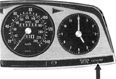
The three catalysts should be changed after 37 500 miles.
The required change of catalyst is indicated by means of a warning lamp in instrument cluster.
|
|||
|
|
|||
|
14.2-050/17 USA 1977/78/79 F2
|
|||
|
|
|||
|
|
|||
|
Change of catalyst indicator
|
|||
|
|
|||
|
Pertinent laws specify that the time for changing the catalyst must be indicated.
On these vehicles the required change is indicated by a „CATALYST” warning lamp.
Note: Since tourist vehicles are not provided with catalysts, the following instructions must be observed:
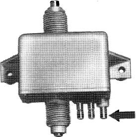
The catalyst mileage counter is attached underneath instrument panel and is driven by tachometer shaft. When the required mileage is attained, a contact closes and the „CATALYST” warning lamp lights up.
|
|||
|
|
|||
|
Model 1 23
|
1543-7317
|
||
|
|
|||
|
When the „CATALYST” warning lamp lights up, open contact in mileage counter by means of pin (arrow) to extinguish warning lamp.
|
|||
|
|
|||
|
107-10095
 |
|||
|
|
|||
|
14.2-050/18 USA 1977/78/79 F2
|
|||
|
|
|||
|
|
||
|
E. Air injection tourist vehicles Federal version
|
||
|
|
||
|
Tourist vehicles are supplied ex factory without a catalyst.
For this reason, only the air injection is different from standard equipment.
To reduce the incompletely burnt components in exhaust gas, air is injected into hot zone behind exhaust valves.
Afterburning is controlled via the engine temperature and vacuum conditions in intake pipe.
To prevent backfiring in exhaust, the air injection is shut off in given driving ranges.
|
||
|
|
||
 |
||
|
|
||
|
Components of air injection:
Except for catalyst, components are similar to Federal version.
|
||
|
|
||
|
14.2-050/19 USA 1977/78/79 F2
|
||
|
|
||
|
|
|||
|
Operation
Starting at a coolant temperature of approx. 17 °C in cylinder head air is discharged into exhaust ducts of cylinder head at idle speed, during deceleration and under partial load.
The air pump is driven by the crankshaft via a V-belt and delivers constantly air when the engine is running. The air flows to pressure relief valve (74) which discharges the excess air delivered at high speeds into the open air starting at a backpressure of approx. 0.266 bar.
From pressure relief valve (74) th excess air is diverted into the exhaust ducts of the cylinder head via the diverter valve (41), and starting at approx. 17 °C coolant temperature via the check valve (42), while below approx. 17 °C coolant temperature the excess air is discharged into the open air through the air filter for silencing (45).
|
 |
||
|
SO7-1312C
|
|||
|
|
|||
|
14.2-050/20 USA 1977/78/79 F2
|
|||
|
|
|||
|
|
|||||||||||||||||||||||||||||||||||||||||||||||||||||||||||||||||||||||||||
|
F. Air injection tourist vehicles California version
|
|||||||||||||||||||||||||||||||||||||||||||||||||||||||||||||||||||||||||||
|
|
|||||||||||||||||||||||||||||||||||||||||||||||||||||||||||||||||||||||||||
|
Tourist vehicles are supplied ex factory without a catalyst.
For this reason, only the air injection is different from standard equipment.
To reduce the incompletely burnt components in exhaust gas, air is injected into hot zone behind exhaust valves.
|
|||||||||||||||||||||||||||||||||||||||||||||||||||||||||||||||||||||||||||
|
|
|||||||||||||||||||||||||||||||||||||||||||||||||||||||||||||||||||||||||||
|
Afterburning is controlled via the engine temperature and vacuum conditions in intake pipe.
To prevent backfiring in exhaust, the air injection is shut off in given driving ranges.
|
|||||||||||||||||||||||||||||||||||||||||||||||||||||||||||||||||||||||||||
|
|
|||||||||||||||||||||||||||||||||||||||||||||||||||||||||||||||||||||||||||
|
40
1073-7536
|
||||||||||||||||||||||||||||||||||||||||||||||||||||||||||||||||||||||||||
|
|
|||||||||||||||||||||||||||||||||||||||||||||||||||||||||||||||||||||||||||
|
Components of air injection:
Except for catalyst and the air injection line in-between the small catalysts, the components are similar to the California version.
|
|||||||||||||||||||||||||||||||||||||||||||||||||||||||||||||||||||||||||||
|
|
|||||||||||||||||||||||||||||||||||||||||||||||||||||||||||||||||||||||||||
|
14.2-050/21 USA 1977/78/79 F2
|
|||||||||||||||||||||||||||||||||||||||||||||||||||||||||||||||||||||||||||
|
|
|||||||||||||||||||||||||||||||||||||||||||||||||||||||||||||||||||||||||||
|
|
|||
|
Operation
The air pump (40) is driven by the crankshaft via a V-belt and delivers constantly air when the engine is running. The air flows to pressure relief valve (74) which discharges the excess air delivered at high speeds into the open air starting at a backpressure of approx. 0.266 bar.
|
 |
||
|
|
|||
|
From pressure relief valve (74) the air is diverted via air switch-over valve (41) either into injection ducts in cylinder head or is discharged into the open air through air filter (for silencing).
The air switch-over by means of air switch-over valve is controlled by thermovalve 17 °C (61) and 50 °C (73).
There are three temperature ranges:
|
|||
|
|
|||
|
1. Coolant temperature below 17 °C (air discharge into open air)
The thermovalve 17 °C (61) is closed, the thermovalve 50 °C (73) is open. No vacuum flows to diaphragm of air switch-over valve (41), the diaphragm is positively vented by the vent cap on valve. The compression spring in air switch-over valve closes the injection line to cylinder head. The delivered air is discharged into the open air through the air filter (for silencing).
2. Coolant temperature above 17 °C and below 50 °C
(air injection into cylinder head)
The thermovalve 17 °C (61) and the thermovalve 50 °C (73) are open. The vacuum from intake pipe flows to diaphragm of air switch-over valve (41) and the diaphragm is pushed upwards against force of spring. The injection line to cylinder head is opened, the discharge line into the open air is closed. The air is injected via check valve (42) into exhaust ducts of cylinder head.
|
 |
||
 |
|||
|
|
|||
|
14.2-050/22 USA 1977/78/79 F2
|
|||
|
|
|||
|
|
||||
|
3. Coolant temperature above 50 °C (air discharge into the open air)
Thermovalve 17 °C (61) is open, thermovalve 50 °C (73) is closed. No additional vacuum flows to diaphragm of air switch-over valve. The diaphragm chamber is positively vented (connected to atmosphere) via vent cap on valve. The compression spring in air switch-over valve closes the injection line to cylinder head. The delivered air is discharged into the open air through air filter (for silencing).
|
 |
|||
|
|
||||
|
G. Fuel evaporation control model year 1977
|
||||
|
|
||||
|
A fuel evaporation control system has been installed to improve emissions which are not directly connected with engine combustion.
|
||||
|
|
||||
|
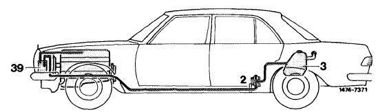
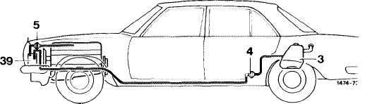
Function diagram
|
 |
|||
|
2 Valve system
3 Fuel tank
39 Charcoal canister
|
||||
|
|
||||
|
Components of f ue! evaporation control system:
|
 |
|||
|
Valve system
The valve system is mounted underneath vehicle at level of rear leg room.
The valve system comprises three valves:
1. Negative vent valve
2. Pressure relief valve
3. Positive vent valve
|
||||
|
|
||||
|
14.2-050/23 USA 1977/78/79 F2
|
||||
|
|
||||
|
|
||||
|
The negative vent valve opens at a slight overpressure. The evaporation vapours are flowing via negative vent valve (1, direction B) into a line toward charcoal canister.
The pressure relief valve opens as a safety valve in the event of an overpressure in fuel evaporation system. The fuel vapours are bled directly into the open air.
The positive vent valve opens whenever cooling down of fuel tank results in a vacuum.
 |
||||
|
|
||||
|
1 Negative vent valve
2 Pressure relief valve
3 Positive vent valve
A To valve/to expansion tank
B To charcoal canister
C Fresh air inlet
D Outlet pressure relief valve
|
||||
|
|
||||
|
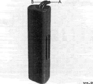
Charcoal canister
The fuel evaporation vapours from fuel tank are stored in charcoal canister and are drawn again out of canister when driving.
|
 |
|||
|
A Connection tank vent B Draw-off connection
|
||||
|
|
||||
|
Throttle valve housing
The throttle valve housing is provided with a connection to draw evaporation vapours from charcoal canister.
|
 |
■S87-J3G53
|
||
|
1 Vacuum connection ignition adjustment retard
2 Vacuum connection ignition adjustment advance
3 Vacuum connection charcoal canister
|
||||
|
|
||||
|
14.2-050/24 USA 1977/78/79 F2
|
||||
|
|
||||
|
|
|||
|
Operation
The fuel evaporation vapours from fuel tank are routed to charcoal canister via valve system (2).
In the charcoal canister the fuel evaporation vapours are stored when the engine is stopped and are drawn off into throttle valve housing starting at a given throttle valve position when the engine is running.
|
|||
|
|
|||
|
H. Fuel evaporation control system model year 1978/79
A fuel evaporation control system has been installed to improve emissions which are not directly connected with engine combustion.
|
|||
|
|
|||
|
Function diagram
|
|||
|
|
|||
|
3 Fuel tank
4 Vent valve unit
5 Regenerating valve (purge valve) 39 Charcoal canister
 |
|||
|
|
|||
|
Components of fuel evaporation control system:
|
 |
||
|
Vent valve unit
The vent valve unit is mounted underneath vehicle at level of rear leg room and replaces the valve system known from model year 1977. The unit comprises a pressure relief valve and a vacuum relief valve.
|
|||
|
|
|||
|
14.2-050/25 USA 1977/78/79 F2
|
|||
|
|
|||
|
|
|||
|
Charcoal canister
The fuel evaporation vapours from fuel tank are stored in charcoal canister and are drawn again out of canister when driving.
|
 |
||
|
A Draw-off connection B Tank vent connection
|
|||
|
|
|||
|
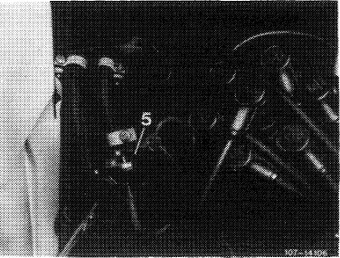
Regenerating valve (purge valve)
The regenerating valve (5) is located in regenerating line (purge line) from charcoal canister to throttle valve housing.
|
 |
||
|
|
|||
|
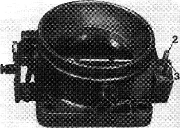
Throttle valve housing
To avoid mixing up of vacuum connections, the OD of the vacuum connection (3) to charcoal canister has been increased from 4 to 5 mm. Two regenerating bores (purge bores) were mounted above throttle valve for drawing off evaporation vapours from charcoal canister.
|
 |
||
|
2 Vacuum connection ignition advance
3 Vacuum connection charcoal canister
|
|||
|
|
|||
|
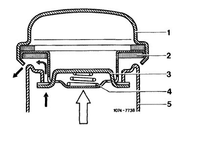
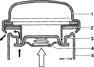
Fuel tank cap
To avoid increased overpressure in fuel tank, the fuel tank cap has been modified.
|
 |
||
|
1 Cap
2 Sealing ring
3 Clamp
4 Compression spring
5 Filler neck
|
|||
|
|
|||
|
14.2-050/26 USA 1977/78/79 F2
|
|||
|
|
|||
|
|
||||
|
Operation
|
||||
|
|
||||
|
Evaporation system
When the pressure in the fuel tank reaches 30—50 mbar, the pressure relief valve (4) in vent unit opens allowing the fuel vapours to flow to the charcoal canister where they are stored if the engine is not running.
The pressure in fuel tank is increased to 30—50 mbar by the vent valve unit (4). As a result, less fuel vapours can escape from fuel tank.
|
||||
|
|
||||
|
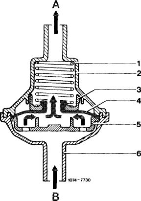
Vent valve unit open to charcoal canister
|
 |
|||
|
1 Compression spring
2 Valve housing
3 Spring seat
4 Pressure relief valve
5 Valve disc
|
6 Positive vent valve
7 Connection
A Connection charcoal canister
B Connection fuel tank
|
|||
|
|
||||
|
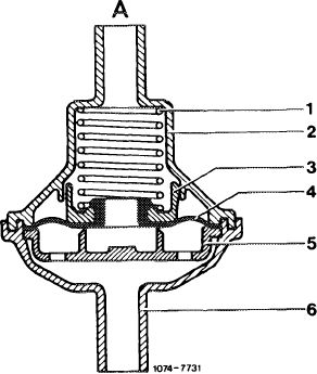
Vent valve unit open to fuel tank
|
 |
|||
|
|
||||
|
14.2-050/27 USA 1977/78/79 F2
|
||||
|
|
||||
|
|
|||
|
When the fuel cools down, the smaller volume is compensated by the intake of air or fuel evaporation vapours from charcoal canister via vacuum relief valve (6) starting at a vacuum of 7-16 mbar. If the vacuum in fuel tank drops below 1 mbar, the vacuum relief valve (6) will close.
|
|||
|
|
|||
|
If the pressure in the fuel tank increases above 0.1—0.3 bar due to a malfunction in the fuel evaporation system, the fuel vapours escape via the fuel tank cap.
|
 |
||
|
1 Tank cap
2 Sealing ring
3 Clamp
4 Compression spring
5 Filler neck
|
|||
|
|
|||
|
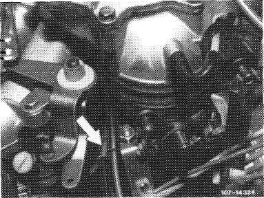
Regenerating system (purge system)
The charcoal canister is connected to the throttle valve housing by means of a line in which the regenerating valve (purge valve) is enclosed.
|
 |
||
|
Arrow = throttle valve draw-off connection
|
|||
|
|
|||
|
When the engine is running and the vacuum in the regenerating line (purge line) exceeds 30—50 mbar, the regenerating valve (purge valve) opens. The fuel vapours stored in charcoal canister can be drawn off depending on the throttle valve position.
|
|||
|
|
|||
|
14.2-050/28 USA 1977/78/79 F 2
|
|||
|
|
|||
|
|
|||
|
Regenerating valve (purge valve) open
1 Compression spring
2 Valve housing
3 Spring seat
4 Pressure relief valve
5 Valve disc
6 Connection
A Connection throttle valve housing
B Connection charcoal canister
|
 |
||
|
|
|||
 |
|||
|
|
|||
|
Regenerating valve (purge valve) closed
|
|||
|
|
|||
|
When opening the throttle valve the two regenerating bores (purge bores) in throttle valve housing which are entering a common duct are both passed over one after the other. As a result, regeneration in lower partial load range begins in dosages which are not influencing the driving characteristics.
At idle and during deceleration (throttle valve closed) the two regenerating bores are at atmospheric side of throttle valve. The regenerating valve is closed, there is no regeneration of charcoal in canister.
|
|||
|
|
|||
|
14.2-050/29 USA 1977/78/79 F2
|
|||
|
|
|||
|
|
||||
|
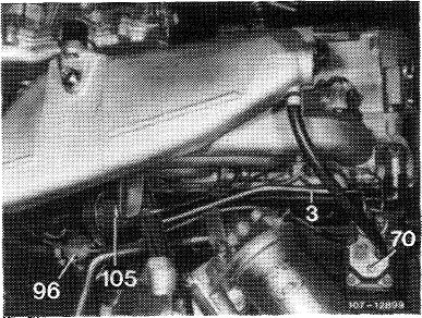
I. Vehicles for Federal control system higher altitudes model year 1977
|
||||
|
|
||||
|
Vehicles for Federal control system for higher altitudes are provided with the Federal emission control system and differ only by the warming-up governor (70).
The warming-up governor carries the following designation:
|
 |
|||
|
MB part no.
|
000 070 12 61
|
|||
|
Bosch no.
|
0 438 140 041
|
|||
|
|
||||
|
14.2-050/30 USA 1977/78/79 F2
|
||||
|
|
||||