Checking injection nozzles
|
|
||||||||||||||||||||||||||||||||||
|
07.1—135 Checking injection nozzles
|
||||||||||||||||||||||||||||||||||
|
|
||||||||||||||||||||||||||||||||||
|
Job no. of flat rates or standard texts and flat rates data 07—6712.
|
||||||||||||||||||||||||||||||||||
|
|
||||||||||||||||||||||||||||||||||
|
Test values injection nozzles
|
||||||||||||||||||||||||||||||||||
|
|
||||||||||||||||||||||||||||||||||
|
||||||||||||||||||||||||||||||||||
|
|
||||||||||||||||||||||||||||||||||
|
) The difference between any two injection nozzles within one engine must not exceed 5 bar positive.
) Starting production code no. 928 or 041.
) Starting November 1981 with center bore 0.20 mm dia. (formerly 0.15 mm dia.)
|
||||||||||||||||||||||||||||||||||
|
|
||||||||||||||||||||||||||||||||||
|
Tightening torques
|
Nm
|
|||||||||||||||||||||||||||||||||
|
|
||||||||||||||||||||||||||||||||||
|
||||||||||||||||||||||||||||||||||
|
Cleaner
|
 |
000 589 00 68 00
|
||||||||||||||||||||||||||||||||
|
|
||||||||||||||||||||||||||||||||||
|
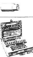
Conventional tools
|
||||||||||||||||||||||||||||||||||
|
|
||||||||||||||||||||||||||||||||||
|
Torque wrench 1/2″ drive, 40-130 Nm
|
||||||||||||||||||||||||||||||||||
|
|
||||||||||||||||||||||||||||||||||
|
Tester EFEP 60 H
|
e.g. Bosch, D-7000 Stuttgart Order No.
 |
|||||||||||||||||||||||||||||||||
|
|
||||||||||||||||||||||||||||||||||
|
Cleaning needles 0.13 mm dia.
|
e.g. Bosch, D-7000 Stuttgart Order No. KDEP 2900/3
|
|||||||||||||||||||||||||||||||||
|
|
||||||||||||||||||||||||||||||||||
|
Cleaning needles 0.18 mm dia.
|
e.g. Bosch, D-7000 Stuttgart Order No. KDEP 2900/5
|
|||||||||||||||||||||||||||||||||
|
|
||||||||||||||||||||||||||||||||||
|
Note
|
||||||||||||||||||||||||||||||||||
|
|
||||||||||||||||||||||||||||||||||
|
For testing always use clean testing oil or filtered diesel fuel. Be sure never to hold your hand in the jet from an injection nozzle. For the jet would penetrate your skin, destroy the tissue beneath, enter your bloodstream and possibly give you blood poisoning.
|
||||||||||||||||||||||||||||||||||
|
|
||||||||||||||||||||||||||||||||||
|
07.1.8-135/1 F3
|
||||||||||||||||||||||||||||||||||
|
|
||||||||||||||||||||||||||||||||||
|
|
|||
|
Attention:
Be sure to close the pressure gage tap for checking jet and rattling noise because pressure gage may otherwise be damaged by excessive increase in pressure.
|
|||
|
|
|||
|
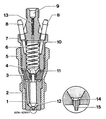
The engine is equipped with a center hole pintle nozzle which is distinguished from the standard pintle by a cross hole and a center hole (14 and 15) in the thrust pin. Moreover, a maintenance-free edge filter (13) is pressed into upper part (7) of the injection nozzle holder.
|
 |
||
|
1 Needle valve
2 Nozzle body
3 Nozzle holder insert
4 Thrust pin
5 Injection nozzle holder, lower part
6 Compression spring
7 Injection nozzle holder, upper part
8 Leak-off connection
9 Fuel inlet
10 Steel shim
11 Annular groove and inlet ports
12 Pressure chamber in nozzle body
13 Edge filter
14 Cross hole
15 Center hole
|
|||
|
|
|||
|
Checking
|
 |
||
|
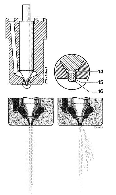
1 Prior to checking: Check center hole (47) with cleaning needle of 0.18 mm dia. for passage. On nozzles with 0.15 mm ID, check pintle with cleaning needle 0.13 mm dia. for passage.
2 Thoroughly pump injection nozzle 5 times on tester. Then check buzzing, actuating hand lever slowly for this purpose (at least 1 stroke per second).
|
|||
|
3 Check jet: At short, fast partial strokes (at least 2 strokes per second) the jet must be rather closed and break well.
|
|||
|
A Jet pattern closed and well atomized
B Jet pattern torn up, too wide and spreading
|
|||
|
|
|||
|
07.1.8-135/2 F3
|
|||
|
|
|||
|
|
|||
|
4 Establish initial jet by moving hand lever slowly down (4—6 s/stroke).
A vertical cord-like jet must come out of center hole (15).
Note: On new nozzles, the initial jet is very difficult to produce, for this reason check center hole with cleaning needle 0.18 mm dia. for passage.
|
 |
||
|
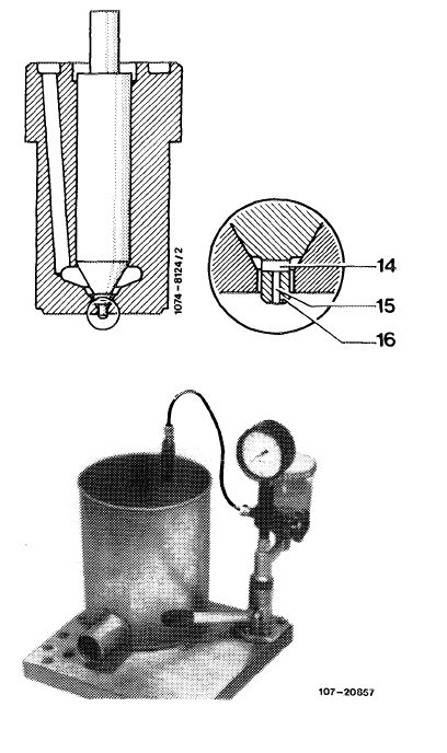
5 Checking ejection pressure:
Nominal value: 135—143 bar with new nozzle, at least 120 bar with used nozzle.
At slow downward movement of hand lever (approx. 1 stroke per second) read ejection pressure on pressure gauge.
Shutoff valve must be open for checking.
|
|||
|
|
|||
|
07.1.8-135/3 F3
|
|||
|
|
|||