Checking vacuum shutoff for leaks
|
|
||
|
07.1—150 Checking vacuum shutoff for leaks
|
||
|
|
||
|
Job no. of flat rates or standard texts and flat rates data 07-8222 or 8225.
|
||
|
|
||
|
A. Without Tester
|
||
|
|
||
|
Note concerning diaphragm vacuum pump
Installed:
Model 116 up to model year 1979.
Model 116 starting model year 1980,123 and
126 are provided with piston vacuum pumps.
If engine oil appears in vacuum lines or brake booster, you may find that the diaphragm in the vacuum control unit or the one in the vacuum pump is defective.
The appearance of engine oil necessitates the replacement of the vacuum control unit and also of the vacuum lines carrying oil. The vacuum pump will have to be repaired and the brake booster exchanged if they show oil at the vacuum line connection.
Leakage through the vacuum pump diaphragm or through the vacuum control unit at the injection pump will allow engine oil to reach the combustion chambers through the suction pipe, causing a higher combustion temperature which may damage the precombustion chambers.
If the full length of the vacuum lines is a dark black it may be assumed that engine oil has entered the combustion chamber. In this case you are advised to check all the precombustion chambers.
Precombustion chambers which are cracked at the bottom or have burnt (scaly) ball pin surfaces, have to be exchanged because engine damage due to breaking precombustion chamber parts will otherwise have to be taken into account.
|
||
|
|
||
|
Checking
|
||
|
|
||
|
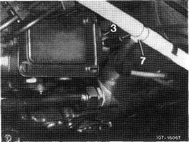
1 Run engine.
2 Disconnect vacuum line (brown) at Tee piece (7) and check whether pressure is negative or not.
|
||
|
|
||
|
07.1.8-150/1 F3
|
||
|
|
||
|
|
|||
|
a) Should this not be the case, unscrew vacuum line with Tee piece at vacuum pump and brake booster.
Check throttle in Tee piece for obstructions, blowing out with compressed air if necessary.
Note: On vehicles with diaphragm vacuum pump. If throttle is oiled up, diaphragm in vacuum pump may be defective. Throttle is defective, if engine oil shows up at connection of vacuum line (pump end). Reconditioning of vaccuum pump is described in repair instructions brakes model 115 and 123 (42—620).
|
|||
|
|
|||
|
b) If pressure at Tee piece is negative, connect vacuum control unit (3) straight to Tee piece (7) via a hose.
The vacuum from vacuum pump (8) now acts direct
on the diaphragm in vacuum control unit (3) and
draws the injection pump control rod to the stop
position.
Exchange the vacuum control unit if engine does
not stop immediately (07.1—220).
|
 |
||
|
|
|||
|
Immediate stoppage of engine means that vacuum control unit is in good working order. In this case, trouble may be due to sticking of valve (Din steering lock. Exchange valve with reference to repair instructions for steering system models 115 and 123 (46-640).
Attention:
Do not cross vacuum lines when reconnecting.
|
|||
|
|
|||
|
3 Run engine. Check vacuum control unit and valve in steering lock for satisfactory operation, and examine injection pump for leakage.
|
|||
|
|
|||
|
07.1.8-150/2 F2
|
|||
|
|
|||
|
|
|||||||||||||||||||||||||||||||||||||||||||||||||||||||||||
 |
|||||||||||||||||||||||||||||||||||||||||||||||||||||||||||
|
|
|||||||||||||||||||||||||||||||||||||||||||||||||||||||||||
|
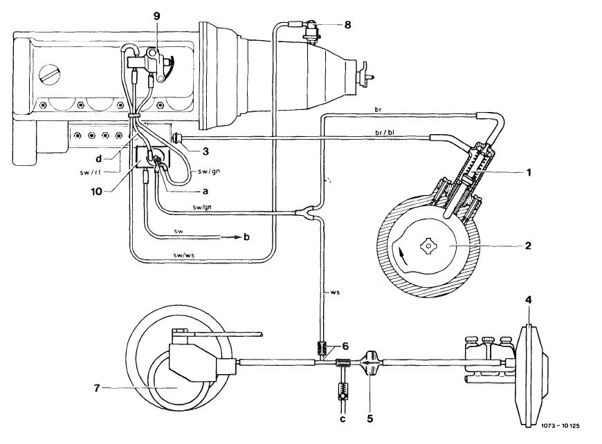
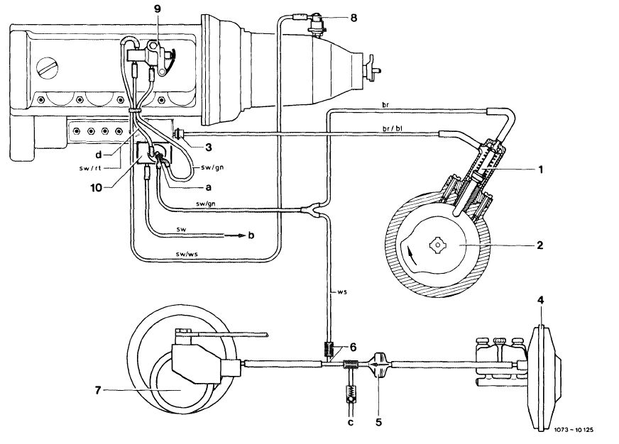
br = brown br/bl = brown/blue sw/rt = black/red sw/gn = black/green sw = black sw/ws = black/white
|
||||||||||||||||||||||||||||||||||||||||||||||||||||||||||
|
|
|||||||||||||||||||||||||||||||||||||||||||||||||||||||||||
|
07.1.8-150/3
|
|||||||||||||||||||||||||||||||||||||||||||||||||||||||||||
|
|
|||||||||||||||||||||||||||||||||||||||||||||||||||||||||||
|
|
||||||||||||||||||||||||||||||||||||||||||||
|
B. With tester
|
||||||||||||||||||||||||||||||||||||||||||||
|
|
||||||||||||||||||||||||||||||||||||||||||||
|
Data
|
||||||||||||||||||||||||||||||||||||||||||||
|
|
||||||||||||||||||||||||||||||||||||||||||||
|
||||||||||||||||||||||||||||||||||||||||||||
|
|
||||||||||||||||||||||||||||||||||||||||||||
|
Tester for vacuum and gauge pressure
|
 |
201 589 13 21 00
|
||||||||||||||||||||||||||||||||||||||||||
|
|
||||||||||||||||||||||||||||||||||||||||||||
|
Checking
|
 |
|||||||||||||||||||||||||||||||||||||||||||
|
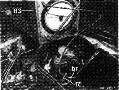
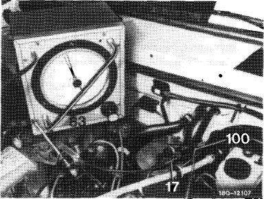
1 Turn ignition key in steering lock to position „2”.
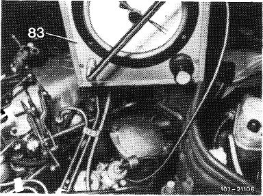
2 Pull brown line (br) out of connection (17) and connect tester (83) to brown line (br).
|
||||||||||||||||||||||||||||||||||||||||||||
|
|
||||||||||||||||||||||||||||||||||||||||||||
|
07.1.8-150/4 F3
|
||||||||||||||||||||||||||||||||||||||||||||
|
|
||||||||||||||||||||||||||||||||||||||||||||
|
|
|||
|
Evacuate tester (83).
|
 |
||
|
|
|||
|
4 Rising pressure on gage means that key starting system valve at steering lock is subject to leakage.
5 Exchange key starting system valve at steering lock (46-640).
Attention:
Prior to exchanging key starting system valve and vacuum control unit of injection pump, check hose lines and connectors.
|
 |
||
|
|
|||
|
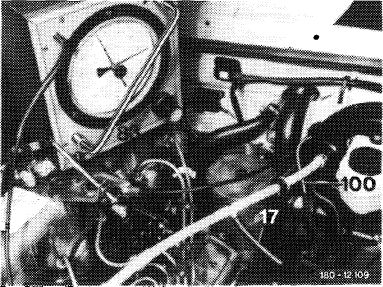
6 Turn ignition key in steering lock back to position „1” or”0″.
7 Evacuate system using tester (83).
8 Rising pressure on gage may imply that vacuum control unit or valve is subject to leakage.
|
 |
||
|
|
|||
|
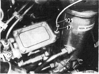
9 Disconnect control line (101) with connector (17) from vacuum control unit of injection pump.
|
 |
||
|
|
|||
|
07.1.8-150/5 F2
|
|||
|
|
|||
|
|
||||||||||||||||||||||||||||||||||||||||||||||||||||||||||||||||||||
|
10 Connect tester (83) to vacuum control unit and evacuate.
11 Rising pressure on gage means that vacuum control unit of injection pump is subject to leakage.
12 Exchange vacuum control unit of injection pump (07.1-220).
13 Constant pressure on gage means that vacuum control unit of injection pump is in order and that key starting valve is subject to leakage. Exchange key starting system valve (46—640).
|
 |
|||||||||||||||||||||||||||||||||||||||||||||||||||||||||||||||||||
|
|
||||||||||||||||||||||||||||||||||||||||||||||||||||||||||||||||||||
 |
||||||||||||||||||||||||||||||||||||||||||||||||||||||||||||||||||||
|
|
||||||||||||||||||||||||||||||||||||||||||||||||||||||||||||||||||||
|
1 Valve
2 Cam
3 Vacuum control unit
4 Brake booster
5 Check valve
|
|
br =brown br/bl = brown/blue sw/rt = black/red sw/gn = black/green sw = black sw/ws = black/white
|
||||||||||||||||||||||||||||||||||||||||||||||||||||||||||||||||||
|
|
||||||||||||||||||||||||||||||||||||||||||||||||||||||||||||||||||||
|
07.1.8-150/6 F3
|
||||||||||||||||||||||||||||||||||||||||||||||||||||||||||||||||||||
|
|
||||||||||||||||||||||||||||||||||||||||||||||||||||||||||||||||||||