Removal and installation of injection pump
|
|
||||||||||||||||||||||||||||||||||||
|
07.1—200 Removal and installation of injection pump
|
||||||||||||||||||||||||||||||||||||
|
|
||||||||||||||||||||||||||||||||||||
|
Job no. of flat rates or standard texts and flat rates data 8410 or 8411, 8430, 8431.
|
||||||||||||||||||||||||||||||||||||
|
|
||||||||||||||||||||||||||||||||||||
|
Survey model — engine — injection pump
|
||||||||||||||||||||||||||||||||||||
|
|
||||||||||||||||||||||||||||||||||||
|
Model Engine
|
|
|||||||||||||||||||||||||||||||||||
|
|
||||||||||||||||||||||||||||||||||||
|
Standard version up to 1980
|
||||||||||||||||||||||||||||||||||||
|
|
||||||||||||||||||||||||||||||||||||
|
123.193 617.952
|
PES 5 MW 55/320 RS 16
|
RW 375/2200 MW 28-1
|
FP/K 22 MW 22
|
3.0 g
5th edition
|
||||||||||||||||||||||||||||||||
|
|
||||||||||||||||||||||||||||||||||||
|
Standard version starting 1981
|
||||||||||||||||||||||||||||||||||||
|
|
||||||||||||||||||||||||||||||||||||
|
123.193 617.952
|
PES 5 MW 55/320 RS 16
|
RW 375/2200 MW 28-33)
|
FP/K 22MW8
|
3.0 g
1st edition
|
||||||||||||||||||||||||||||||||
|
|
||||||||||||||||||||||||||||||||||||
|
(usa) 1978/1979 Identification: Green type rating plate
|
||||||||||||||||||||||||||||||||||||
|
|
||||||||||||||||||||||||||||||||||||
|
116.120 617.950
|
PES 5 MW 55/320 RS 16
|
RW 375/2200 MW 22
|
FP/K 22MW8
|
3.0 g
4th edition
|
||||||||||||||||||||||||||||||||
|
|
||||||||||||||||||||||||||||||||||||
|
(usa) 1980
|
||||||||||||||||||||||||||||||||||||
|
|
||||||||||||||||||||||||||||||||||||
|
RW 375/2200 MW 22
|
||||||||||||||||||||||||||||||||||||
|
|
||||||||||||||||||||||||||||||||||||
|
116.120 617.950
|
PES 5 MW 55/320 RS 16
|
RW 375/2200 MW 282
|
FP/K 22 MW 22
|
3.0 g
4th edition
|
||||||||||||||||||||||||||||||||
|
|
||||||||||||||||||||||||||||||||||||
|
(usa) 1981
|
||||||||||||||||||||||||||||||||||||
|
|
||||||||||||||||||||||||||||||||||||
|
123.193 617.952
|
PES 5 MW 55/320 RS 16
|
RW 375/2200 MW 28-1
|
FP/K 22MW22
|
3.0 g
5th edition
|
||||||||||||||||||||||||||||||||
|
126.120 617.951
|
||||||||||||||||||||||||||||||||||||
|
|
||||||||||||||||||||||||||||||||||||
|
<@) starting model year 1982
|
||||||||||||||||||||||||||||||||||||
|
|
||||||||||||||||||||||||||||||||||||
|
123.133
123.153 617.952
123.193
|
PES 5 MW 55/320 RS 16
|
RW 375/2200 MW 28-3
|
FP/K 22MW22
|
3.0 m
1st edition
|
||||||||||||||||||||||||||||||||
|
126.120 617.951
|
||||||||||||||||||||||||||||||||||||
|
|
||||||||||||||||||||||||||||||||||||
|
07.1.8-200/1 F3
|
||||||||||||||||||||||||||||||||||||
|
|
||||||||||||||||||||||||||||||||||||
|
|
||||||||||||||||||||||||||
|
(usa) starting model year 1984 California
|
||||||||||||||||||||||||||
|
|
||||||||||||||||||||||||||
|
123.133
123.153 617.952
123.193
|
PES 5 MW 55/320 RS 16-1
|
RW 375/2200 MW28-33)
|
FP/K 22 MW 22
|
3.0 m
1st edition
|
||||||||||||||||||||||
|
|
||||||||||||||||||||||||||
|
126.120 617.951
|
||||||||||||||||||||||||||
|
|
||||||||||||||||||||||||||
|
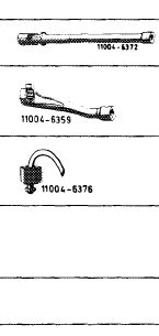
’ Accurate checkup and adjustment of injection pump is possible on an injection pump test bench only. For workshops, where
. such a test bench is installed, test sheets for the different pumps are available.
’ Entering production starting February 1980.
’ Reference impulse verification (RIV), dynamic injection timing (begin of delivery) test possible.
|
||||||||||||||||||||||||||
|
|
||||||||||||||||||||||||||
|
||||||||||||||||||||||||||
|
|
||||||||||||||||||||||||||
|
Special tools
Socket 13 mm, 3/8″ drive
Box wrench socket open, 17 mm, 1/2″ drive for injection lines
Overflow pipe
Conventional tool
Torque wrench 1/2″ drive, 15-65 Nm
|
 |
000 589 21 07 22 000 589 68 03 00
636 589 02 23 00
|
||||||||||||||||||||||||
|
|
||||||||||||||||||||||||||
|
07.1.8-200/2 F3
|
||||||||||||||||||||||||||
|
|
||||||||||||||||||||||||||
|
|
|||
|
Removal
|
 |
||
|
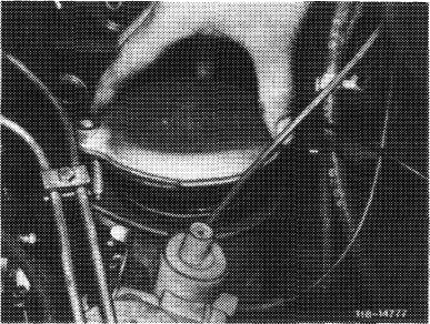
1 Detach vacuum line at vacuum control unit and at vacuum control valve for automatic transmission.
2 Unscrew delivery line at aneroid compensator.
|
|||
|
|
|||
|
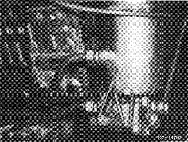
3 Disconnect electric cable at temperature sensor, detach control rod, unscrew injection lines and fuel lines at injection pump. Clip caps onto connections for injection lines and fuel hoses at injection pump.
|
|||
|
|
|||
|
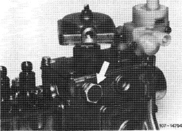
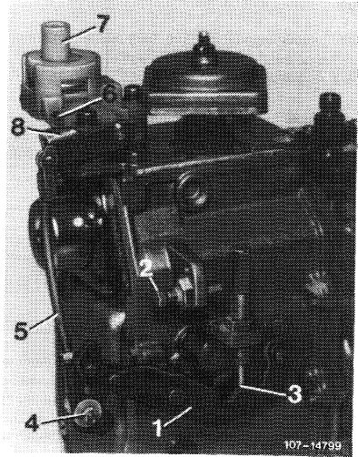
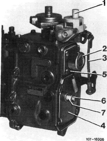
4 Unscrew lubricating oil line (5).
Attention:
Prior to removal of lubricating oil line (5), clean connecting points.
|
 |
||
|
|
|||
|
5 Unscrew and remove upper part of oil filter so that engine oil can return to oil pan.
|
 |
||
|
|
|||
|
07.1.8-200/3 F2
|
|||
|
|
|||
|
|
|||
|
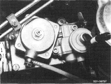
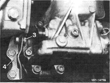
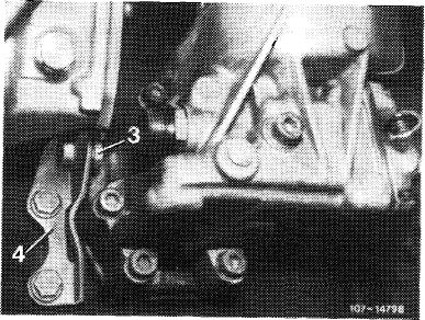
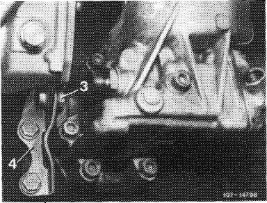
6 Unscrew hex-head bolts at supporting holder (4) as well as 3 nuts holding injection pump. Release feastening bolt (3) to provide adjustment within oblong hole.
|
 |
||
|
|
|||
|
7 Unscrew all engine oil lines at oil filter body, releasing clamps for this purpose.
8 Unscrew and remove oil filter body from crankcase (18-110).
Attention:
When removing gasket, make sure that no remains drop into oil passages.
9 Withdraw injection pump from crankcase. Detach coupling sleeve from injection pump driver or from drive shaft.
|
 |
||
|
|
|||
|
Note: If driver is to be exchanged, lock driver with serrated wrench and release hexagon nut. Then remove driver from injection pump shaft using puller. Clean axle stub and driver, making sure that both cones are absolutely clean and dry.
When fitting a new driver, note Woodruff key and marks (arrows).
|
 |
||
|
|
|||
|
Installation
|
|||
|
|
|||
|
Attention:
Prior to installing a replacement injection pump, remove screw plug (arrow) and fill with 0.4 I engine oil (first filling).
|
 |
||
|
|
|||
|
07.1.8-200/4 F2
|
|||
|
|
|||
|
|
||||
|
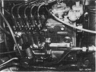
10 Check whether connecting rod (5) is correctly set, moving control lever (1) to full-load stop (2) for this purpose. Operating lever (8) must have approx. 0.5 mm clearance from full-load stop (6).
If necessary, adjust connecting rod (5) at adjustable knuckle (4).
|
 |
|||
|
1 Control lever
2 Full-load stop
3 Idle speed stop
4 Adjustable knuckle
5 Connecting rod
|
6 Full-load stop at vacuum control valve
7 Vacuum control valve
8 Operating lever for vacuum control valve
|
|||
|
|
||||
|
11 Detach supporting holder (4) from removed injection pump and bolt to injection pump for installation. Do not tighten fastening bolt (3) because adjustment within oblong hole is still necessary.
|
 |
|||
|
|
||||
|
12 Move crankshaft to start of delivery in compression stroke.
|
 |
|||
|
|
||||
|
07.1.8-200/5 F2
|
||||
|
|
||||
|
|
|||
|
13 Fit new gasket.
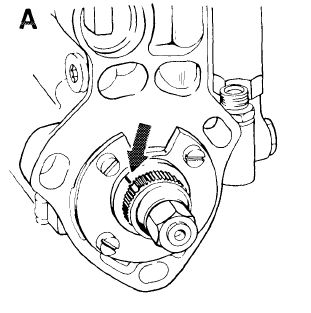
14 Move injection pump to mark, turning injection pump camshaft until mark on camshaft agrees with line on flange (arrow).
Attention!
On Bosch production code number „251” (November 1982) the mark for begin of delivery may be applied to the wrong spot on bearing cap.
|
 |
||
|
Mark on bearing cap correct
(approx. center of bearing cap screw)
|
|||
|
|
|||
|
Note
|
 |
||
|
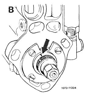
When installing an injection pump with wrong mark on bearing cap, the pinion should be positioned in such a manner that the recess is 3 teeth to the left on the mark of the bearing cap. In this position the injection pump is at begin of delivery (basic position). The engine should be at 24° before TDC, as usual.
|
|||
|
Marking on bearing cap wrong
(approx. lefthand edge recess of oil overflow)
|
|||
|
|
|||
|
15 Slip coupling sleeve onto driver and insert injection pump. Fit washers and slightly tighten fastening nuts of injection pump.
16 Check and adjust start of delivery (07.1-110 and 115).
|
|||
|
|
|||
|
17 Tighten injection pump fastening nuts and attach supporting holder (4) to crankcase. Now tighten fastening bolt (3) in oblong hole of supporting holder. Supporting holder is to be fastened with shims as per part No. 116 990 14 40 and hex-head bolts M 8x 16.
18 Reconnect lubricating oil line to injection pump.
|
 |
||
|
|
|||
|
07.1.8-200/6 F3
|
|||
|
|
|||
|
|
|||
|
19 Fit oil filter and oil filter cover with new seal.
20 Connect all oil lines to oil filter.
21 Attach temperature sensor cable, connect charge air line and vacuum lines to injection pump, and fit all fuel lines.
|
 |
||
|
|
|||
|
22 Vent injection system with hand delivery pump (07.1-140).
23 Check throttle linkage and adjust, if required {30-300).
24 Run engine to operating temperature and check all connections for leaks.
25 Check idle speed and adjust, if required (07.1- 100).
|
|||
|
|
|||
|
26 Adjust damper for regulator. If a damper (6) is installed on regulator of injection pump, adjust at idle against transverse vibrations of engine.
For this purpose, loosen counter nut (7).
Adjust damper (6) at idle speed, screwing damper in until transverse engine vibrations have been remedied. Then tighten counter nut (7) to 20—25 Nm.
|
 |
||
|
6 Damper
7 Counter nut
|
|||
|
|
|||
|
07.1.8-200/7 F3
|
|||
|
|
|||
|
|
|||||
|
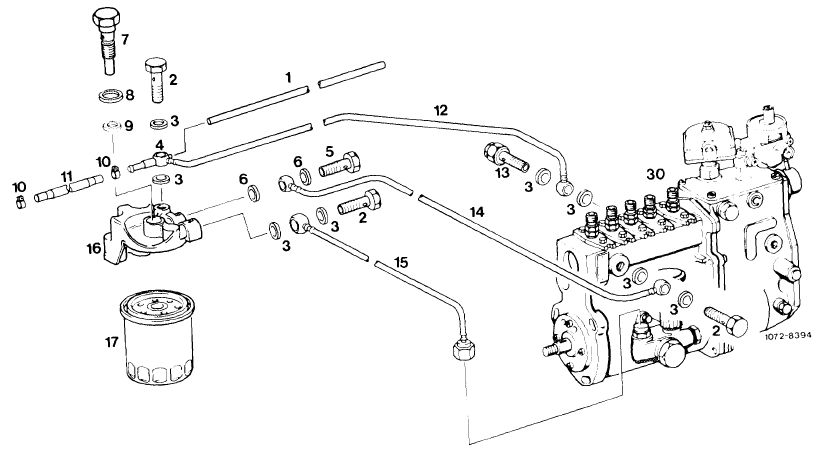
Fuel filter
|
|||||
|
|
|||||
 |
|||||
|
|
|||||
|
1
2 3 4 5 6
|
Leak-off hose from injection nozzle
Union screw
Sealing ring
Banjo connector
Union screw
Sealing ring
|
7 Union screw
8 Sealing ring
9 O-ring
10 Hose clamp
11 Expansion hose
12 Return line from bypass valve
|
13 Bypass valve
14 Fuel line
15 Fuel line
16 Upper part of fuel filter
17 Fuel filter
30 Injection pump
|
||
|
|
|||||
|
07.1.8-200/8 F3
|
|||||
|
|
|||||
|
|
||||||||||||||||||||||||||||||||||||||||||||||||||||||||||||||||||||||||||||||||||||||||||||||||||||||||||||||||||||||||||||||||||||||||||||||||||||||||||||||||||||||||||||||||||
|
Mixture Control
|
||||||||||||||||||||||||||||||||||||||||||||||||||||||||||||||||||||||||||||||||||||||||||||||||||||||||||||||||||||||||||||||||||||||||||||||||||||||||||||||||||||||||||||||||||
|
|
||||||||||||||||||||||||||||||||||||||||||||||||||||||||||||||||||||||||||||||||||||||||||||||||||||||||||||||||||||||||||||||||||||||||||||||||||||||||||||||||||||||||||||||||||
 |
||||||||||||||||||||||||||||||||||||||||||||||||||||||||||||||||||||||||||||||||||||||||||||||||||||||||||||||||||||||||||||||||||||||||||||||||||||||||||||||||||||||||||||||||||
|
|
||||||||||||||||||||||||||||||||||||||||||||||||||||||||||||||||||||||||||||||||||||||||||||||||||||||||||||||||||||||||||||||||||||||||||||||||||||||||||||||||||||||||||||||||||
|
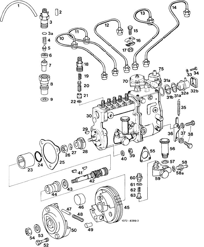
Socket
Segment for injection timing device
Centrifugal weight
Pin
Compression spring
Pin
Segmental flange
Waisted bolt
Washer
Nut
Gasket
Hand-operated fuel feed pump
Rubber sealing ring
Socket
Sealing ring
Fuel feed pump
Screwed union
Sealing ring
Compression spring
Delivery and suction valve
Aneroid compensator
Vacuum control valve
|
|||||||||||||||||||||||||||||||||||||||||||||||||||||||||||||||||||||||||||||||||||||||||||||||||||||||||||||||||||||||||||||||||||||||||||||||||||||||||||||||||||||||||||||||||
|
|
||||||||||||||||||||||||||||||||||||||||||||||||||||||||||||||||||||||||||||||||||||||||||||||||||||||||||||||||||||||||||||||||||||||||||||||||||||||||||||||||||||||||||||||||||
|
07.1.8-200/9 F3
|
||||||||||||||||||||||||||||||||||||||||||||||||||||||||||||||||||||||||||||||||||||||||||||||||||||||||||||||||||||||||||||||||||||||||||||||||||||||||||||||||||||||||||||||||||
|
|
||||||||||||||||||||||||||||||||||||||||||||||||||||||||||||||||||||||||||||||||||||||||||||||||||||||||||||||||||||||||||||||||||||||||||||||||||||||||||||||||||||||||||||||||||