Checking injection timing (begin of delivery) (high pressure method)
|
|
|||||
|
07.1—109 Checking injection timing (begin of delivery) (high pressure method)
Job no. of flat rates or standard texts and flat rates data 07—8234.
|
|||||
|
|
|||||
|
Test values
|
|||||
|
|
|||||
|
Injection timing (begin of delivery) before TDC in compression stroke
|
+24° +1°
|
||||
|
|
|||||
|
Attention!
Push regulating lever of injection pump to full load while measuring and pull vacuum hose from vacuum control unit.
|
|||||
|
|
|||||
|
Tightening torque
|
Nm
|
||||
|
|
|||||
|
Injection lines
|
25
|
||||
|
|
|||||
|
Special tools
|
|||||
|
|
|||||
|
Box end wrench element, open 17 mm, 1/2″ square for injection lines
|
 |
005 589 68 03 00
|
|||
|
|
|||||
|
Pump unit, complete
|
 |
617 589 00 71 00
|
|||
|
|
|||||
|
Connecting members with carrying case
|
 |
617 589 00 91 00
|
|||
|
|
|||||
|
Quick lock
|
 |
617 589 02 91 00
|
|||
|
|
|||||
|
*J W „^11004-TO3O2
|
|||||
|
|
|||||
|
Closing bracket
|
 |
617 589 03 91 00
|
|||
|
110O4-10300
|
|||||
|
|
|||||
|
Drive square 1/2″, 80 mm long for rotating engine
|
 |
617 589 00 16 00
|
|||
|
|
|||||
|
Conventional tool
|
|||||
|
|
|||||
|
Torque wrench 1/2″ square, 15—65 Nm
|
|||||
|
|
|||||
|
07.1.8-109/1 F3
|
|||||
|
|
|||||
|
|
|||
|
Checking
1 Clean injection lines in range of coupling nuts on injection pump as well as on fuel filter.
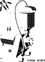
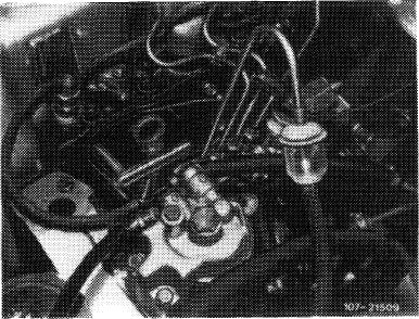
2 Set control rod of injection pump to full load. For this purpose, pull control lever (1) to full load stop (2).
For this purpose, pull vacuum hose from vacuum control unit and lock regulating lever of injection pump to full load.
|
 |
||
|
1 Regulating lever
2 Full throttle stop
|
|||
|
|
|||
|
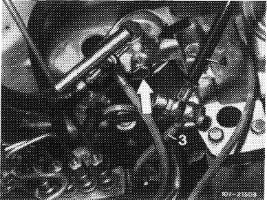
3 Unscrew injection line for cylinder 1.
On injection pump, screw on test line with sight glass and install return line to fuel tank of pump unit.
|
 |
||
|
|
|||
|
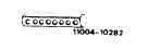
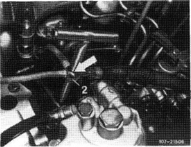
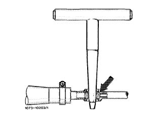
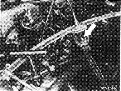
4 Close fuel return line from injection pump to fuel filter.
Insert O-ring into ring member (2) of return line and firmly push in quick lock.
|
 |
||
|
|
|||
|
07.1.8-109/2 F3
|
|||
|
|
|||
|
|
|||
|
Inserting quick lock into fuel return line
|
 |
||
|
|
|||
|
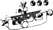
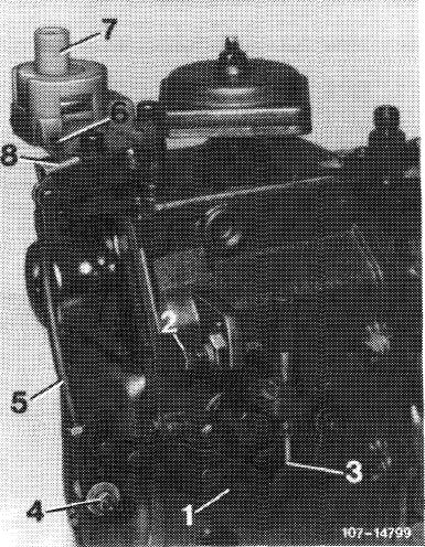
5 Connect supply line (3) for injection pump with connecting line (4) of pump unit by means of a double hollow screw. Close connecting holes on fuel filter with closing plugs (arrows).
|
 |
||
|
|
|||
|
6 Clamp connecting cable of pump unit to vehicle battery (red terminal positive, black terminal negative).
7 Rotate crankshaft in direction of rotation of engine up to approx. 35 before TDC in compression stroke of first cylinder. Engage pump unit.
Attention!
Engage pump unit only up to measuring. In the event of a leaking injection nozzle, fuel may enter combustion chamber.
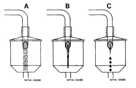
8 Slowly rotate crankshaft in direction of rotation of engine, while watching fuel jet in sight glass.
Delivery begins when the fuel jet changes over into a formation of droplets.
In this position, read begin of delivery on graduated scale on balancing disk.
|
 |
||
|
Nominal value: 24° + 1°
|
|||
|
|
|||
|
07.1.8-109/3 F3
|
|||
|
|
|||
|
|
|||||
|
A Full fuel jet
B Fuel jet constricted,
shortly before begin of delivery C Formation of droplets, begin of delivery
|
 |
||||
|
|
|||||
|
9 Disconnect pump unit. Assemble injection system.
10 Ventilate injection system (07.1 — 140). Run engine and check all connections for leaks.
|
|||||
|
|
|||||
 |
|||||
|
|
|||||
|
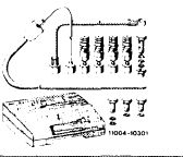
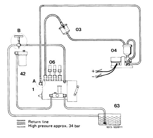
Connection diagram high pressure overflow method
|
|||||
|
|
|||||
|
1 Injection pump
2 Fuel filter
3 Sight glass
|
4 Pump unit
5 Fuel tank
|
A Hollow screw, fuel feed from pump unit
B Fuel return line with quick lock or closing bracket closed
|
|||
|
|
|||||
|
07.1.8-109/4 F3
|
|||||
|
|
|||||