Checking injection timing (begin of delivery) (flow pressure method)
|
|
|||||||||||||||||||||||||||||||||
|
07.1—110 Checking injection timing (begin of delivery) (flow pressure method)
Job no. of flat rates or standard texts and flat rates data 07—8228 or 8231.
|
|||||||||||||||||||||||||||||||||
|
|
|||||||||||||||||||||||||||||||||
|
Test value
|
|||||||||||||||||||||||||||||||||
|
|
|||||||||||||||||||||||||||||||||
|
Start of delivery before TDC in compression stroke
|
+24 ± 1
|
||||||||||||||||||||||||||||||||
|
|
|||||||||||||||||||||||||||||||||
|
Attention!
While conducting measurement, move injection pump control lever to full-load stop and disconnect vacuum hose from vacuum control unit.
|
|||||||||||||||||||||||||||||||||
|
|
|||||||||||||||||||||||||||||||||
|
|||||||||||||||||||||||||||||||||
|
|
|||||||||||||||||||||||||||||||||
|
Special tools
|
|||||||||||||||||||||||||||||||||
|
|
|||||||||||||||||||||||||||||||||
|
|||||||||||||||||||||||||||||||||
|
|
|||||||||||||||||||||||||||||||||
|
Testing
|
 |
||||||||||||||||||||||||||||||||
|
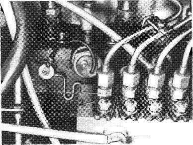
1 Clean injection pump at injection line cap nuts and pipe connections.
2 Pull vacuum line from vacuum control unit.
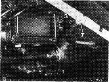
3 Unscrew injection line of No. 1 cylinder.
|
|||||||||||||||||||||||||||||||||
|
|
|||||||||||||||||||||||||||||||||
|
07.1.8-110/1 F3
|
|||||||||||||||||||||||||||||||||
|
|
|||||||||||||||||||||||||||||||||
|
|
|||
|
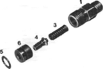
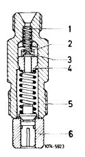
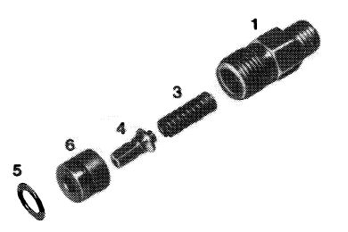
4 Unscrew pipe connection (1) of first injection pump element, removing compression spring (3) and delivery valve (4).
|
 |
||
|
1 Pipe connection
3 Compression spring
4 Delivery valve
5 Copper sealing ring
6 Delivery valve carrier
|
|||
|
107-10319/2
|
|||
|
|
|||
|
Attention:
Do not unscrew assembly (2) because injection pump will otherwise have to be re-adjusted on injection pump test rig.
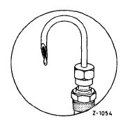
5 Screw pipe connection back in and attach overflow pipe.
|
107-9822
|
||
|
1 Pipe connection
2 Element assembly
|
|||
|
|
|||
|
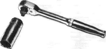
6 Using wrench and socket, turn crankshaft in normal direction until crank angle is just short of start of delivery in compression stroke of first cylinder.
|
 |
||
|
|
|||
|
R100/649%
|
|||
|
|
|||
|
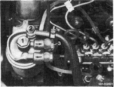
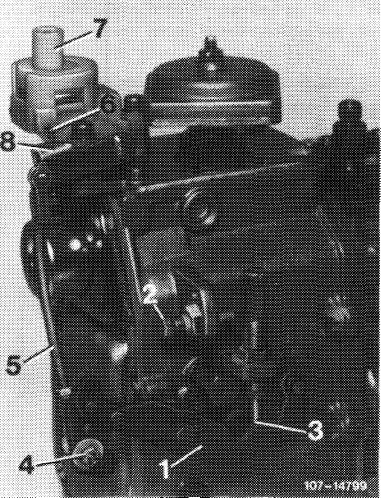
7 Open union screw (2) at fuel filter and fill fuel filter using hand feed pump to make fuel run out of overflow pipe.
|
 |
||
|
|
|||
|
07.1.8-110/2 F2
|
|||
|
|
|||
|
|
|||
|
Attention:
While conducting measurement, move injection pump control lever to full load and detach vacuum hose from vacuum control unit.
|
 |
||
|
1 Control lever
2 Full-load stop
3 Idle stop
|
|||
|
|
|||
|
8 Turn crankshaft in direction of rotation until fuel at overflow pipe takes the shape of droplets. Droplet formation: one droplet per second.
Note: On pipe connections with relief throttles (2), no full fuel jet comes out of overflow pipe, but measuring accuracy is not influenced.
|
 |
||
|
|
|||
|
9 While maintaining this position, note start of delivery in degrees on balance disk. Adjust start of delivery if necessary (07.1—115).
10 Unscrew overflow pipe and pipe connection.
|
 |
||
|
|
|||
|
07.1.8-110/3 F3
|
|||
|
|
|||
|
|
|||
|
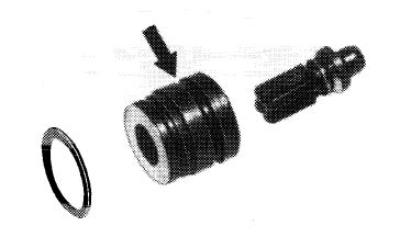
11 Remove delivery valve holder (6), checking whether delivery valve (4) moves freely in holder (6).
12 Insert delivery valve holder (6) with annular groove pointing downward.
Attention:
The copper sealing ring (5) is located beneath the delivery valve holder and need not be exchanged.
|
|||
|
|
|||
|
Up to Bosch production date „248” (August 1982)
1 Pipe connection
3 Compression spring
4 Delivery valve
5 Copper sealing ring
6 Delivery valve carrier
|
 |
||
|
1O7-I031S/2
|
|||
|
|
|||
|
Note: Starting Bosch production date „249” (September 1982) modified delivery valve carriers will be installed. On these carriers, the ring groove must be pointing upwards.
|
 |
||
|
Starting Bosch production date „249′ (September 1982)
Arrow = modified version with additional ring groove
|
|||
|
|
|||
|
107-25354
|
|||
|
|
|||
|
13 Slightly lubricate threads of pipe connection (1), screw-in and tighten to 40—50 Nm in one step.
14 Fit injection line and vent injection system (07.1-140).
15 Run engine and check all connections for leakage. Any pipe connection that is leaking has to be exchanged. In this case, remember to exchange copper sealing ring beneath delivery valve holder (07.1-210).
|
|||
|
|
|||
|
07.1.8-110/4 F3
|
|||
|
|
|||