Removing and installing tensioning rail
|
|
||||||||||||||||||||||||||||||||||||||||
|
05—330 Removing and installing tensioning rail
|
||||||||||||||||||||||||||||||||||||||||
|
|
||||||||||||||||||||||||||||||||||||||||
|
Tightening torques
|
Nm
|
|||||||||||||||||||||||||||||||||||||||
|
|
||||||||||||||||||||||||||||||||||||||||
|
||||||||||||||||||||||||||||||||||||||||
|
|
||||||||||||||||||||||||||||||||||||||||
|
Torque wrench 150—500 Nm (15—50 kpm) 3/4″ square
|
 |
001 589 31 21 00
|
||||||||||||||||||||||||||||||||||||||
|
|
||||||||||||||||||||||||||||||||||||||||
|
Holder
|
 |
110 589 00 40 00
|
||||||||||||||||||||||||||||||||||||||
|
Socket 27 mm, 1/2″ square for rotating engine
|
001 589 65 09 00
|
|||||||||||||||||||||||||||||||||||||||
|
|
||||||||||||||||||||||||||||||||||||||||
|
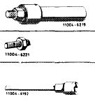
Depressor for valve spring
|
 |
110 589 04 61 00
|
||||||||||||||||||||||||||||||||||||||
|
|
||||||||||||||||||||||||||||||||||||||||
|
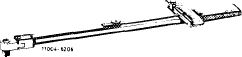
Puller for bearing bolt (basic unit)
|
 |
115 589 20 33 00
|
||||||||||||||||||||||||||||||||||||||
|
M 8 x 30 bolt for extractor
|
115 589 00 34 00
|
|||||||||||||||||||||||||||||||||||||||
|
Wrench socket 10 mm 1/2″ square, 140 mm long
|
000 589 05 07 00
|
|||||||||||||||||||||||||||||||||||||||
|
|
||||||||||||||||||||||||||||||||||||||||
|
Valve adjusting wrench 17 mm
|
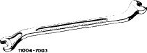 |
110 589 01 01 00
|
||||||||||||||||||||||||||||||||||||||
|
|
||||||||||||||||||||||||||||||||||||||||
|
Chain tensioner holder
|
 |
110 589 02 31 00
|
||||||||||||||||||||||||||||||||||||||
|
|
||||||||||||||||||||||||||||||||||||||||
|
05.2-330/1 F3
|
||||||||||||||||||||||||||||||||||||||||
|
|
||||||||||||||||||||||||||||||||||||||||
|
|
|||||||||||||||||||||||||||||||||||||||
|
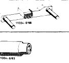
Impact extractor for bearing pin (basic unit)
|
 |
116 589 20 33 00
|
|||||||||||||||||||||||||||||||||||||
|
|
|||||||||||||||||||||||||||||||||||||||
|
|||||||||||||||||||||||||||||||||||||||
|
|
|||||||||||||||||||||||||||||||||||||||
|
Note
|
|||||||||||||||||||||||||||||||||||||||
|
|
|||||||||||||||||||||||||||||||||||||||
|
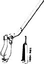
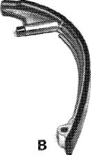
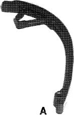
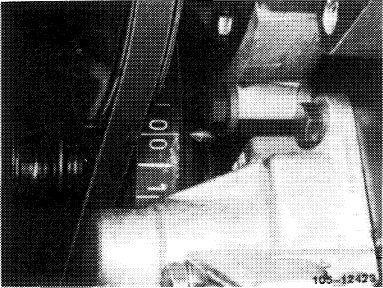
A 1st version tensioning rail (A) can be replaced by a 2nd version tensioning rail (B).
|
 |
 |
|||||||||||||||||||||||||||||||||||||
|
|
|||||||||||||||||||||||||||||||||||||||
|
1OS-12452
|
|||||||||||||||||||||||||||||||||||||||
|
|
|||||||||||||||||||||||||||||||||||||||
|
Removal
|
|||||||||||||||||||||||||||||||||||||||
|
|
|||||||||||||||||||||||||||||||||||||||
|
1 Remove radiator (20-240).
|
|||||||||||||||||||||||||||||||||||||||
|
|
|||||||||||||||||||||||||||||||||||||||
|
2 Remove rocker arms of right camshaft (exhaust) (05-230).
|
 |
||||||||||||||||||||||||||||||||||||||
|
|
|||||||||||||||||||||||||||||||||||||||
|
05.2-330/2 F2
|
|||||||||||||||||||||||||||||||||||||||
|
|
|||||||||||||||||||||||||||||||||||||||
|
|
||||
|
3 Position engine at ignition TDC.
|
 |
|||
|
|
||||
|
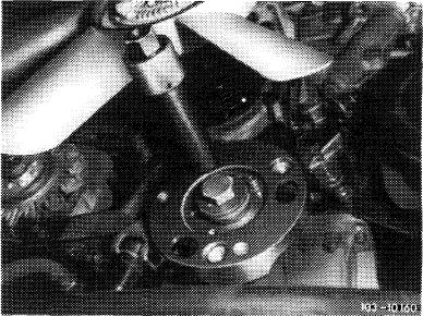
4 Remove vibration damper (03—340). Remove balance disc without bore to extract the tensioning rail bearing pin (03-340).
|
 |
|||
|
|
||||
|
5 Remove chain tensioner (05—310).
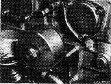
6 Mark relation of left and right camshaft sprockets and timing chain with paint, and remove right camshaft sprocket (1).
|
 |
|||
|
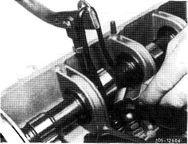
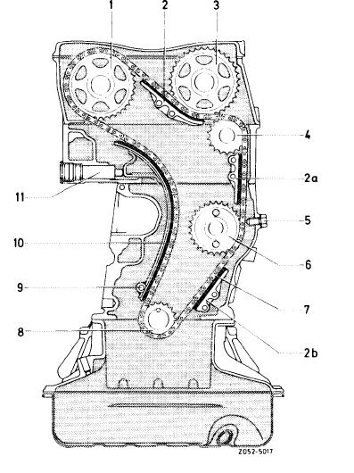
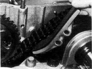
Chain drive
1 Exhaust camshaft sprocket 7
2—2b Sliding rails 8
3 Intake camshaft sprocket 9
4 Guide wheel 10
5 Lock screw 11
6 Intermediate wheel
|
Timing chain Crankshaft sprocket Bearing pin tensioning rail Tensioning rail Hydraulic chain tensioner
|
|||
|
|
||||
|
05.2-330/3 F3
|
||||
|
|
||||
|
|
|||
|
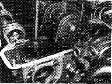
7 Remove sliding rail in camshaft housing.
|
 |
||
|
|
|||
|
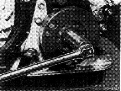
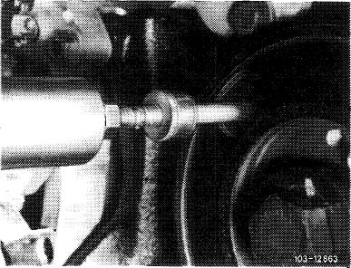
8 Pull out tensioning rail bearing pin with extractor.
|
 |
||
|
|
|||
|
9 Remove tensioning rail upward.
|
 |
||
|
|
|||
|
Installation
|
|||
|
10 Guide in tensioning rail. Coat bearing pin with a sealing compound and knock in.
|
 |
||
|
|
|||
|
05.2-330/4 F2
|
|||
|
|
|||
|
|
|||
|
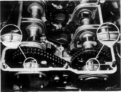
11 Install righthand camshaft sprocket, while paying attention to color symbol on camshaft sprocket and timing chain.
Marks on camshaft sprockets and camshaft housing must align when engine is set at TDC position.
|
 |
||
|
|
|||
|
12 Insall sliding rail in camshaft housing (05—340).
13 Set chain tensioner at assembly position and install (05-310).
14 Install balance disc and vibration damper (03-314).
15 Install rocker arms (05-230).
16 Install radiator.
|
 |
||
|
|
|||
|
05.2-330/5 F2
|
|||
|
|
|||