Removal and installation of camshaft housing
|
|
|||||||||||||||||||||||||||||||||||||||||||||||||
|
01—470 Removal and installation of camshaft housing
|
|||||||||||||||||||||||||||||||||||||||||||||||||
|
|
|||||||||||||||||||||||||||||||||||||||||||||||||
|
Data
|
|||||||||||||||||||||||||||||||||||||||||||||||||
|
|
|||||||||||||||||||||||||||||||||||||||||||||||||
|
|||||||||||||||||||||||||||||||||||||||||||||||||
|
|
|||||||||||||||||||||||||||||||||||||||||||||||||
|
) 0.05 mm more for consistent outside temperatures below —20°C.
|
|||||||||||||||||||||||||||||||||||||||||||||||||
|
|
|||||||||||||||||||||||||||||||||||||||||||||||||
|
|||||||||||||||||||||||||||||||||||||||||||||||||
|
|
|||||||||||||||||||||||||||||||||||||||||||||||||
|
Rocker arm removal and installation tool
|
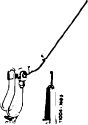 |
110 589 04 61 00
|
|||||||||||||||||||||||||||||||||||||||||||||||
|
|
|||||||||||||||||||||||||||||||||||||||||||||||||
|
Rigid chain tensioner
|
„WJiWiiMIWiirii
11004-7006
|
 |
110 589 03 31 00
|
||||||||||||||||||||||||||||||||||||||||||||||
|
|
|||||||||||||||||||||||||||||||||||||||||||||||||
|
Chain tensioner holder
|
 |
110 589 02 31 00
|
|||||||||||||||||||||||||||||||||||||||||||||||
|
|
|||||||||||||||||||||||||||||||||||||||||||||||||
|
Bearing pin impact extractor (basic unit)
|
 |
116 589 20 33 00
|
|||||||||||||||||||||||||||||||||||||||||||||||
|
|
|||||||||||||||||||||||||||||||||||||||||||||||||
|
|||||||||||||||||||||||||||||||||||||||||||||||||
|
|
|||||||||||||||||||||||||||||||||||||||||||||||||
|
01.2-470/1 F3
|
|||||||||||||||||||||||||||||||||||||||||||||||||
|
|
|||||||||||||||||||||||||||||||||||||||||||||||||
|
|
||||||||||||||||||||||||||||||||||||||||||||||||||||||||||||
|
Valve adjusting wrench 17 mm
|
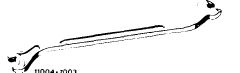 |
110 589 01 01 00
|
||||||||||||||||||||||||||||||||||||||||||||||||||||||||||
|
|
||||||||||||||||||||||||||||||||||||||||||||||||||||||||||||
|
||||||||||||||||||||||||||||||||||||||||||||||||||||||||||||
|
|
||||||||||||||||||||||||||||||||||||||||||||||||||||||||||||
|
Note
|
||||||||||||||||||||||||||||||||||||||||||||||||||||||||||||
|
|
||||||||||||||||||||||||||||||||||||||||||||||||||||||||||||
|
Camshaft housing may only be removed after engine is cold.
The camshaft housing must be removed to remove the camshafts and valve springs or to replace the valve seals.
|
 |
|||||||||||||||||||||||||||||||||||||||||||||||||||||||||||
|
|
||||||||||||||||||||||||||||||||||||||||||||||||||||||||||||
|
105-8003
|
||||||||||||||||||||||||||||||||||||||||||||||||||||||||||||
|
|
||||||||||||||||||||||||||||||||||||||||||||||||||||||||||||
|
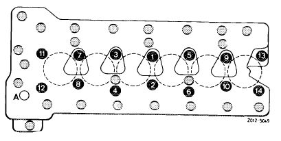
Attention!
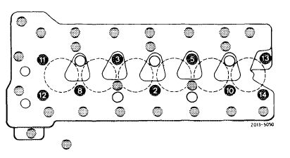
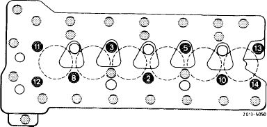
On exchange engines starting unit no. 496.861 (starting October 1977) 9 cylinder head screws with a length of 150 mm are used instead of 145 mm in combination with camshaft housings which are countersunk by 5 mm at the 9 bolt head supporting points 2, 3, 5,8, 10, 11, 12, 13 and 14. These cylinder head bolts must be installed together with a washer part no. 186 990 09 40 (5 mm high), since otherwise the thread lugs in cylinder crankcase may be forced off.
|
 |
|||||||||||||||||||||||||||||||||||||||||||||||||||||||||||
|
|
||||||||||||||||||||||||||||||||||||||||||||||||||||||||||||
|
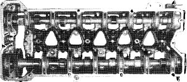
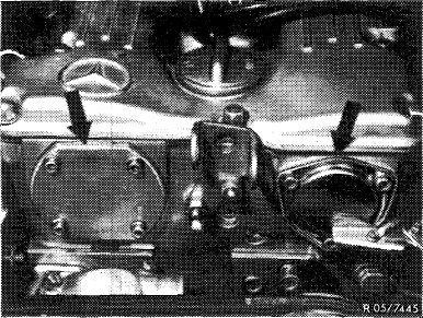
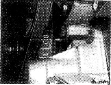
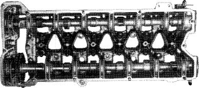
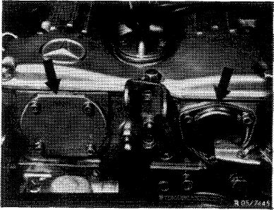
For engines with CIS, use camshaft housing with lug for attaching air cleaner (arrow).
Camshaft housings with repair stages are available
for camshaft with reground bearing journals (01—471).
Exchange engines are in part supplied with camshaft bearing intermediate stages and repair stages (01—471).
Also refer to 01—471, association camshaft housing and camshafts.
|
 |
|||||||||||||||||||||||||||||||||||||||||||||||||||||||||||
|
|
||||||||||||||||||||||||||||||||||||||||||||||||||||||||||||
|
01.2-470/2 F3
|
||||||||||||||||||||||||||||||||||||||||||||||||||||||||||||
|
|
||||||||||||||||||||||||||||||||||||||||||||||||||||||||||||
|
|
|||
|
Removal
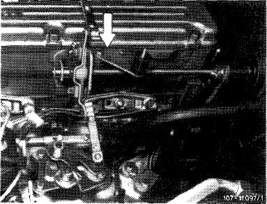
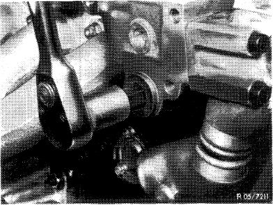
1 Remove pressure oil pump of models with level control and place to one side without disconnecting the lines. This requires loosening only those bolts marked with an arrow.
2 Remove compressor of models with an air conditioner.
|
 |
||
|
|
|||
|
3 Remove vacuum pump of models in USA version.
|
 |
||
|
|
|||
|
4 Drain coolant from radiator and remove upper water hose from engine to radiator. Remove cylinder head cover.
|
 |
||
|
Radiator drain plug of type 123.
|
|||
|
|
|||
|
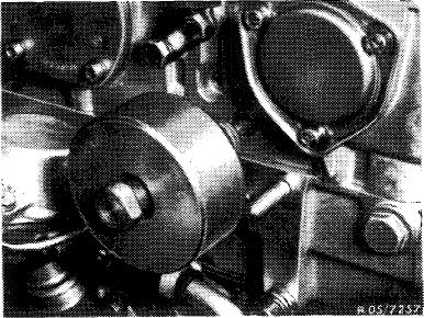
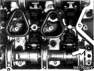
5 Unscrew right cover (arrow) on front of camshaft housing.
|
 |
||
|
|
|||
|
01.2-470/3 F3
|
|||
|
|
|||
|
|
|||
|
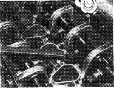
6 Remove all spring clamps with a wrench socket.
|
 |
||
|
|
|||
|
7 Remove all rocker arms with removal and installation tool.
|
 |
||
|
|
|||
|
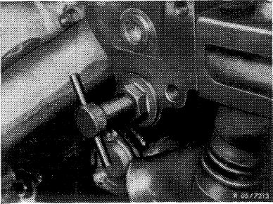
8 Counterhold only the right camshaft (exhaust) with the holding wrench and loosen the camshaft sprocket mounting expansion bolt.
|
 |
||
|
|
|||
|
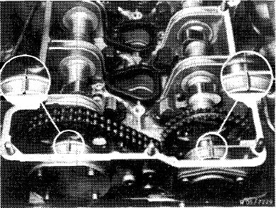
9 Position piston 1 at ignition TDC and both camshafts at marks.
This requires turning the crankshaft with the combination tool.
Attention!
Do not turn engine at the mounting bolts of the camshaft sprockets. Don’t turn engine in reverse direction of rotation.
|
 |
||
|
|
|||
|
01.2-470/4 F3
|
|||
|
|
|||
|
|
|||
|
10 Remove chain tensioner and pressure spring (05-310).
|
 |
||
|
|
|||
|
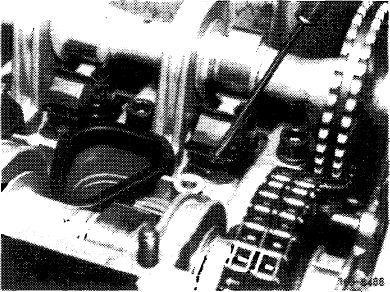
11 Remove sliding rail in camshaft housing. This requires knocking out bearing pins with an impact extractor.
|
 |
||
|
|
|||
|
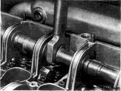
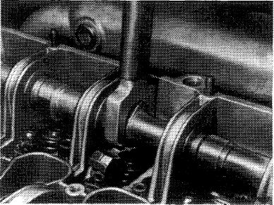
12 Push back righthand camshaft and remove camshaft sprocket.
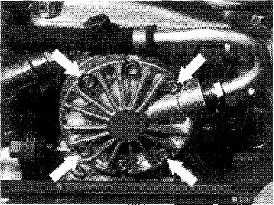
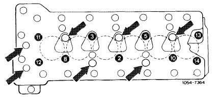
13 Guide camshaft into bearings again. Unscrew M 8 bolts and cylinder head bolts in reverse sequence of tightening.
Do not loosen the 5 cylinder head bolts positioned deeper (arrows) and the 2 M 8 bolts (arrows).
|
 |
||
|
|
|||
|
14 Remove camshaft housing with camshafts.
|
|||
|
|
|||
 |
|||
|
|
|||
|
105-8003
|
|||
|
|
|||
|
01.2-470/5 F3
|
|||
|
|
|||
|
|
|||
|
Installation
|
|||
|
|
|||
|
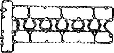
15 Clean mating surface on cylinder head and camshaft housing to remove grease and install sheet metal foil, part number 110 016 06 80, without a sealing compound.
16 Install camshaft housing.
|
 |
||
|
|
|||
|
K>5 -12 589
|
|||
|
|
|||
|
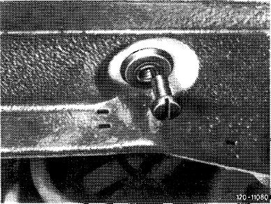
17 Lubricate threads and cylinder head surfaces of cylinder head bolts before installation.
Attention!
Since July of 1974 the clearance on the camshaft housing for 22 mm dia. washer of cylinder head bolt No. 14 has been extended. Use the former 20 mm dia. washer (arrow) on former camshaft housings.
|
 |
||
|
|
|||
|
18 Tighten cylinder head bolts in steps in the sequence of tightening.
1st step: to 70 Nm (7 kpm) starting with bolt No. 2.
|
 |
||
|
|
|||
|
2nd step: all cylinder head bolts to 110 Nm starting with bolt No. 1. This requires first loosening the five cylinder head bolts 1, 4, 6, 7 and 9 located deeper separately somewhat.
Tighten the M 8 bolts from inside to outside to 25 Nm.
Attention!
After tightening all bolts, it must be possible to turn both camshafts by hand.
|
 |
||
|
|
|||
|
01.2-470/6 F3
|
|||
|
|
|||
|
|
|||
|
19 Install right camshaft sprocket making sure that the adjustment marks of both camshafts align when the crankshaft is at TDC.
|
 |
||
|
|
|||
|
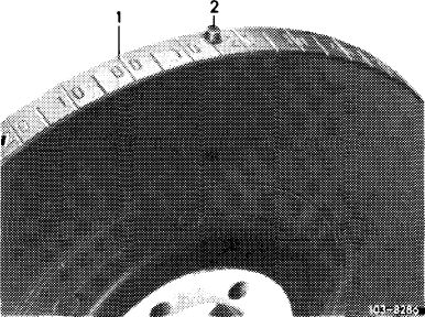
Attention!
When the vibration damper of an engine has a ,,0/0″ mark for BDC in addition to TDC, the TDC mark is next to the pin in the vibration damper.
|
 |
||
|
1 TDC mark
|
|||
|
|
|||
|
20 Install sliding rail so that the timing chain cannot jump.
|
 |
||
|
|
|||
|
21 Install ,,rigid” chain.tensioner and tighten by hand.
Attention!
If camshaft housing has been ground, the timing must be adjusted.
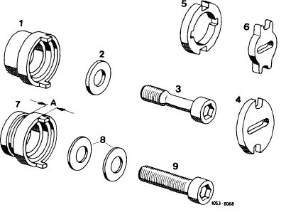
22 Lubricate spacers with engine oil and slide them into camshaft housing.
|
 |
||
|
|
|||
|
01.2-470/7 F3
|
|||
|
|
|||
|
|
|||
|
1 Spacer 2nd version without lubrication groove (for pressure oil pump and vacuum pump 2nd version)
2 Washer
3 Expansion bolt
4 Dog (for pressure oil pump and vacuum pump 2nd version)
5 Dog (for vacuum pump 1st version)
6 Dog 1st version (for oil pump)
7 Spacer 1st version with lubrication groove A = 4.7 mm for vacuum pump 1st version
A = 8.3 mm for pressure oil pump and vacuum pump 2nd version
8 Spring washers (not valid)
9 Mounting bolt (not valid)
|
 |
||
|
|
|||
|
23 Torque expansion bolt for camshaft sprocket to 80 Nm (8 kpm), counterholding camshaft with the holding wrench.
Note: Washer (2) with 30 mm OD is not fitting into spacing sleeve for vacuum pump on USA vehicles up to January 1973. In such a case, machine OD of washer (2) down by approx. 1 mm.
|
 |
||
|
|
|||
|
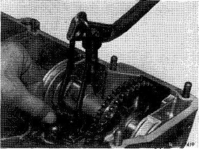
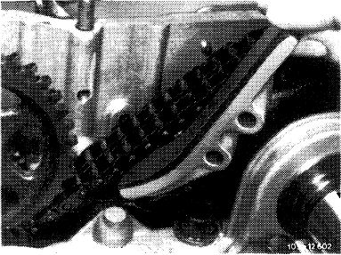
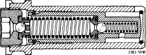
24 Position chain tensioner for installation and install. Also install pressure spring (05—310).
|
 |
||
|
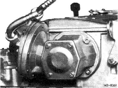
Chain tensioner in installation position
|
|||
|
|
|||
|
25 Install cover on front of camshaft housing and install level control pump or vacuum pump with gaskets.
26 Install rocker arms (05-230).
|
 |
||
|
|
|||
|
01.2-470/8 F3
|
|||
|
|
|||
|
|
|||
|
27 Adjust valve clearance (05-210).
28 Complete engine.
Note: If the camshaft housing has been faced, readjust timing (05—215).
|
 |
||
|
|
|||
|
01.2-470/9 F3
|
|||
|
|
|||