Functional description of exhaust gas turbocharger with aneroid compensator
|
|
|||||
|
09—450 Functional description of exhaust gas turbocharger with aneroid compensator
|
|||||
|
|
|||||
|
A. Exhaust Gas Turbocharger Exhaust gas turbocharger designation
|
|||||
|
|
|||||
|
Garret
|
TA 0301
|
||||
|
|
|||||
|
Kiihnle Kopp and Kausch
|
KKK 532 679 60 31
|
||||
|
|
|||||
|
General
|
|||||
|
|
|||||
|
The exhaust gas turbocharger is a machine using the aerodynamic energy of the exhaust gases to drive a turbine which in turn propels a compressor via a shaft. The turbocharger is located between the exhaust manifold and exhaust pipe, being connected to the engine oil cycle for lubrication and cooling.
A boost pressure control valve on the turbine housing prevents a given boost pressure from being exceeded. In the event of a defective boost pressure control valve, an engine or an engine-transmission overload protection prevents breakdown of engine or transmission.
|
|||||
|
|
|||||
|
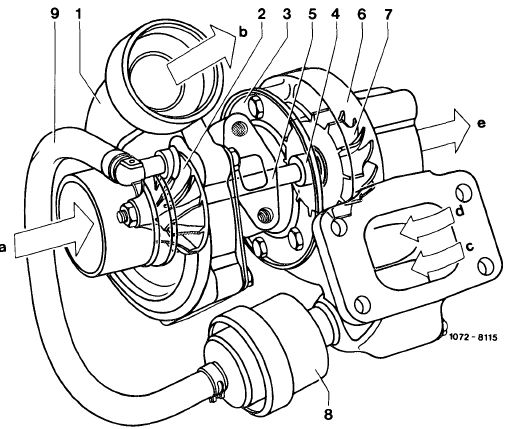
Layout of exhaust gas turbocharger with boost pressure control valve
1 Compressor housing
2 Compressor wheel
3 Center housing
4 Bearings
5 Shaft
6 Turbine housing
7 Turbine wheel
8 Boost pressure control valve
9 Connecting hose
a Compressor intake (fresh air)
b Compressor discharge (compressed air)
c Exhaust gases to bypass duct
d Exhaust gases to turbine wheel
e Exhaust gas discharge
|
 |
||||
|
|
|||||
|
09.8-450/1
|
F 3
|
||||
|
|
|||||
|
|
||||
|
Functional Description
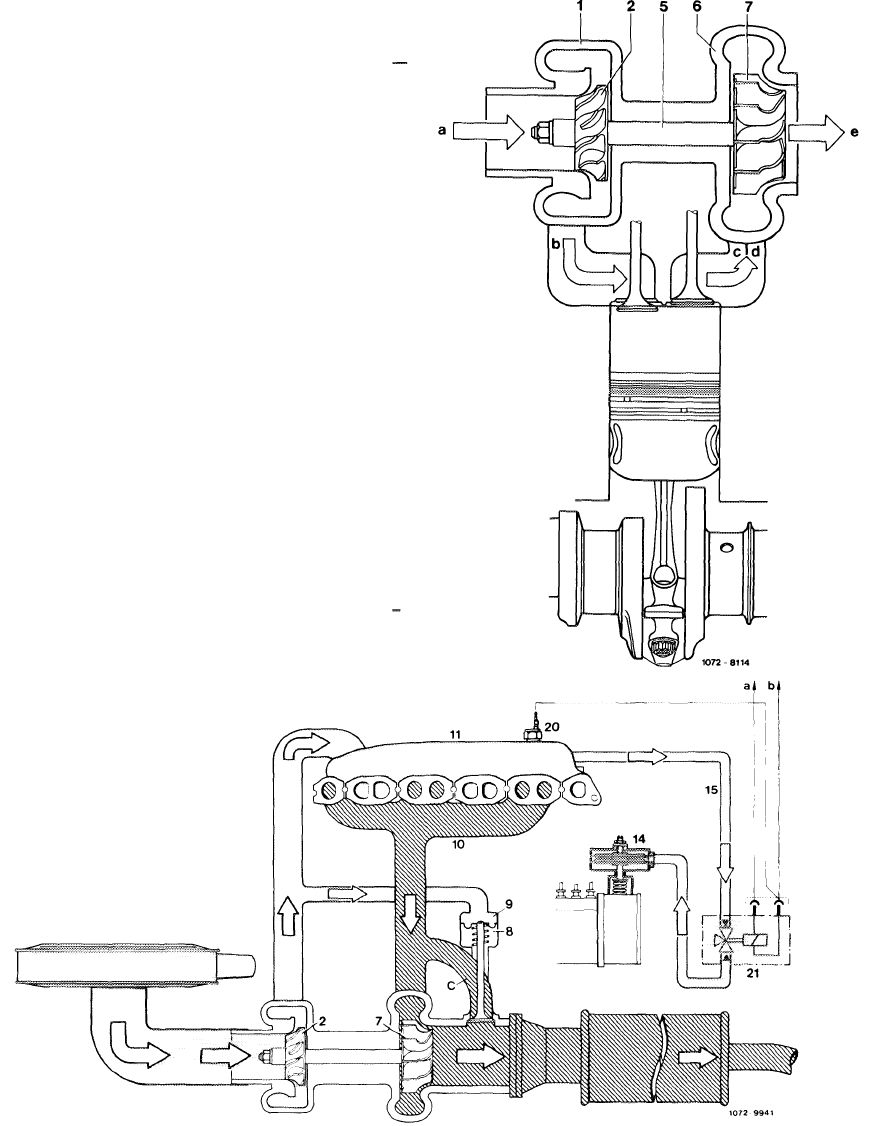
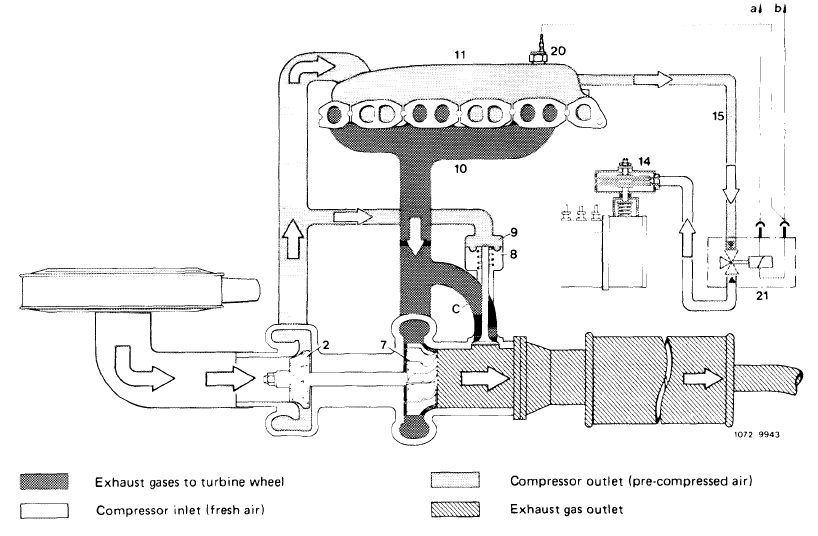
The engine exhaust gases are routed via the exhaust manifold straight to the turbine housing (6) and the turbine wheel (7). The aerodynamic energy of the exhaust gases makes the turbine wheel (7) rotate, driving the compressor wheel (2) which is joined to the turbine wheel (7) via the shaft (5). Maximum speed amounts to about 100,000/min. The fresh air induced by the compressor wheel (2) is compressed and delivered to the engine.
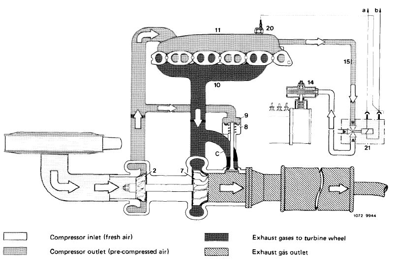
Diagram of fresh air and exhaust gas flow
Compressor housing
Compressor wheel
Shaft
Turbine housing
Turbine wheel
Compressor intake (fresh air)
Compressor discharge (compressed air)
Exhaust gases from exhaust manifold
Exhaust gases from exhaust manifold
Exhaust gas discharge (to exhaust pipe)
1 2 5 6 7 a b c d e
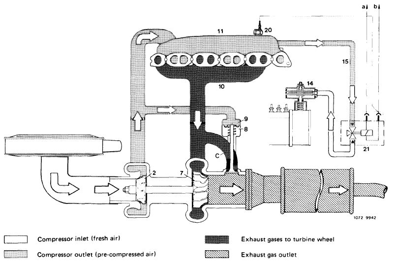
Idle speed and lower partial load
At idle and lower partial load no worthwhile pre-compression will occur, the engine operates as an aspirating engine.
|
||||
|
|
||||
|
Compressor inlet (fresh air)
|
Exhaust gas outlet
|
|||
|
|
||||
|
2 Compressor wheel 11
7 Turbine wheel 14
8 Boost pressure control valve 15
9 Connecting hose 20 10 Exhaust manifold 21
|
Boost air pipe
ALDA capsule
Pressure line
Pressure switch boost air pipe
Changeover valve
|
a Fuse terminal 15
b Switching unit overload protection
c Exhaust gas to bypass duct
|
||
|
|
||||
|
09.8-450/2 F 3
|
||||
|
|
||||
|
|
||||
|
Upper partial load and full load
|
||||
|
|
||||
|
With increasing load and speed, that is, with increasing exhaust gas flow, the turbine wheel (7) is accelerated and the compressor wheel (2) will then generate a boost pressure up to a given value. The compressed charge-air is fed to the indiviual cylinders by way of the boost air (charge-air) pipe. The boost pressure adds increased fuel quantities by way of the ALDA unit on injection pump.
During deceleration, boost pressure is available but fuel injection is stopped due to position of control rod.
|
||||
|
|
||||
 |
||||
|
|
||||
|
2 Compressor wheel 11
7 Turbine wheel 14
8 Boost pressure control valve 15
9 Connecting hose 20 10 Exhaust manifold 21
|
Boost air pipe
ALDA capsule
Pressure line
Pressure switch boost air pipe
Changeover valve overload protection
|
a Fuse terminal 15
b Switching unit overload protection
c Exhaust gas to bypass duct
|
||
|
|
||||
|
09.8-450/3 F 3
|
||||
|
|
||||
|
|
|||
|
Boost Pressure Control Valve
|
|||
|
|
|||
|
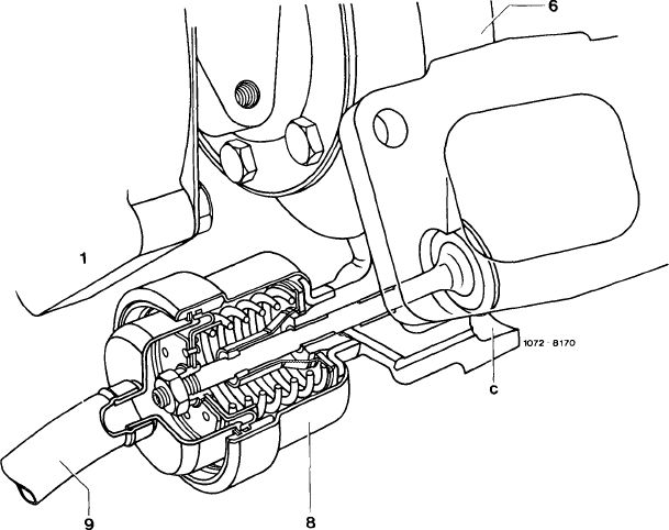
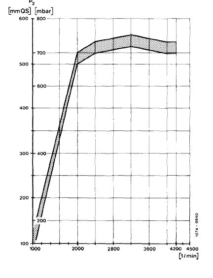
The turbine housing (6) bears a boost pressure control valve (8) designed to prevent the boost pressure from exceeding a given value. The boost pressure is tapped at the compressor housing (1) and passed to the boost pressure control valve (8) via the connecting hose (9). Once a given boost pressure is reached, the boost pressure control valve (8) begins to open the bypass duct (c). Some of the exhaust gases are now able to flow directly into exhaust pipe, keeping the boost pressure at a constant level
 |
|||
|
|
|||
|
1 Compressor housing
6 Turbine housing
8 Boost pressure control valve
9 Connecting hose c Bypass duct
|
 |
||
|
Boost pressure diagram at full load.
|
|||
|
09.8-450/4 F 3
|
|||
|
|
|||
|
|
||||
|
Engine overload protection
|
||||
|
|
||||
|
For overload protection of mechanical engine components a pressure switch is mounted in boost air pipe. If the boost pressure increases above 1.1 ±0.15 bar gauge pressure, the ALDA diaphragm capsule is positively vented via changeover valve and the fuel quantity is restricted to that of an aspirating engine.
|
||||
|
|
||||
 |
||||
|
|
||||
|
2 Compressor wheel 11
7 Turbine wheel 14
8 Boost pressure control valve 15
9 Connecting hose 20 10 Exhaust manifold 21
|
Boost air pipe
ALDA capsule
Pressure line
Pressure switch boost air pipe
Switchover valve overload protection
|
a Fuse terminal 1 5
b Switching unit overload protection
c Exhaust gas to bypass duct
|
||
|
|
||||
|
09.8-450/5 F 3
|
||||
|
|
||||
|
|
||||
|
B. Absolute-measuring boost pressure stop (ALDA)
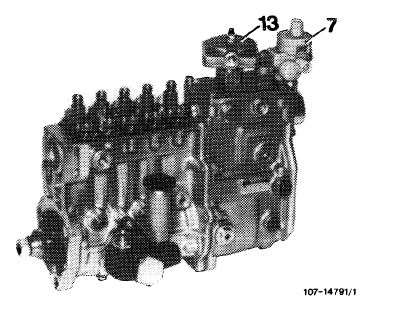
The MW injection pump is provided with an absolute-measuring boost pressure stop (ALDA) and a vacuum control valve (7) for the modulating pressure of the automatic transmission.
The ALDA equipment adapts the injected fuel quantity to the prevailing boost pressure and the respective altitude. As a result, the combustion chambers will always be provided with the correct injected fuel quantity of the respective cylinder charge to provide the best possible efficiency during the various operating modes. The ALDA capsule (13) is connected to the boost pressure pipe by means of a pressure line.
|
 |
|||
|
|
||||
|
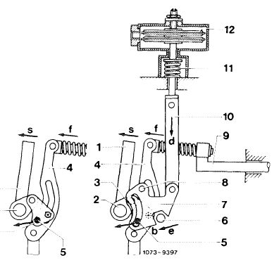
Enrichment by means of boost pressure
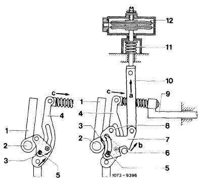
The ALDA unit comprises 2 aneroid capsules (12), a compression spring (11), a connecting rod (10) and the slotted lever (7). Connecting rod (10) is connected to control rod (9) by way of the slotted lever (7), lever (3) and control lever (4). When the boost pressure increases, the aneroid capsules (12) are compressed and, assisted by compression spring (11), will move the connecting rod (10) in direction „a”. This in turn will move the slotted lever (7) within its adjusting range in direction „b” and will push the control rod (9) in direction „c” via coupling lever (3) and control lever (4). The injected fuel quantity is increased.
|
 |
|||
|
ALDA with control linkage
|
||||
|
1 Adjusting lever 7
2 Adjusting lever shaft 8
3 Coupling lever 9
4 Control lever 10
5 Bolt 11
6 Stop 12
|
Slotted lever Pivot (slotted lever) Control rod Connecting rod Compression spring Aneroid capsules
|
|||
|
|
||||
|
09.8-450/6 F 2
|
||||
|
|
||||
|
|
||||
|
Correction at high altitudes
|
 |
|||
|
During operation at high altitudes the aneroid capsules (12) begin to expand due to the increasing atmospheric pressure and force the connecting rod (10) in direction „d” against the compression spring (11).
The slotted lever (7) then moves in direction „e” and hence pushes the control rod (9) in direction „f” via the coupling lever (3) and the control lever (4). The amount of fuel injected begins to drop.
|
||||
|
Transmission overload protection
|
1 2 3
|
|||
|
|
||||
|
For overload protection of automatic transmission in extreme cases, e.g., moving-off uphill with a trailer, two values are decisive in influencing pressure conditions in ALDA aneroid capsule.
Below a modulating pressure of 0.3 bar gauge pressure and at engine speeds > 2000/min, the changeover valve will positively vent the ALDA aneroid capsule and will thereby limit the fuel quantity.
|
||||
|
|
||||
 |
||||
|
|
||||
|
2 Compressor wheel 11
7 Turbine wheel 14
8 Boost pressure control valve 15
9 Connecting hose 20 10 Exhaust manifold 21
|
|
|||
|
Boost air pipe
ALDA capsule
Pressure line
|
a Fuse terminal 1 5
b Switching unit overload protection
c Exhaust gas to bypass duct
|
|||
|
Pressure switch boost air pipe
Changeover valve overload protection
|
||||
|
|
||||
|
09.8-450/7 F 3
|
||||
|
|
||||