Installation and centering of intermediate flange
|
|
||||||||||||||||||||||||||||||||||
|
01—220 Installation and centering of intermediate flange
|
||||||||||||||||||||||||||||||||||
|
|
||||||||||||||||||||||||||||||||||
|
Data
|
||||||||||||||||||||||||||||||||||
|
|
||||||||||||||||||||||||||||||||||
|
Radial runout of intermediate flange
|
max. 0.10
|
|||||||||||||||||||||||||||||||||
|
|
||||||||||||||||||||||||||||||||||
|
Permissible axial runout of intermediate flange
when mounted in crankshaft bearing basic bore during
one full turn.
|
0.10
|
|||||||||||||||||||||||||||||||||
|
|
||||||||||||||||||||||||||||||||||
|
Tightening torques
|
Nm
|
|||||||||||||||||||||||||||||||||
|
|
||||||||||||||||||||||||||||||||||
|
Intermediate flange mounting bolts
|
65
|
|||||||||||||||||||||||||||||||||
|
|
||||||||||||||||||||||||||||||||||
|
Drive plate and flywheel expansion bolt
|
Torque pressure
|
40
|
||||||||||||||||||||||||||||||||
|
|
||||||||||||||||||||||||||||||||||
|
Torque angle
|
90-100°
|
|||||||||||||||||||||||||||||||||
|
|
||||||||||||||||||||||||||||||||||
|
Special tool
|
||||||||||||||||||||||||||||||||||
|
|
||||||||||||||||||||||||||||||||||
 |
||||||||||||||||||||||||||||||||||
|
|
||||||||||||||||||||||||||||||||||
|
Dial gage holder (two required)
|
121 589 00 21 00
|
|||||||||||||||||||||||||||||||||
|
|
||||||||||||||||||||||||||||||||||
|
||||||||||||||||||||||||||||||||||
|
|
||||||||||||||||||||||||||||||||||
|
Note
|
||||||||||||||||||||||||||||||||||
|
|
||||||||||||||||||||||||||||||||||
|
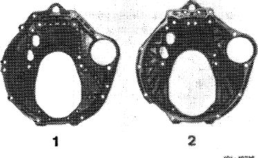
A replaced intermediate flange must be centered. The automatic transmission W4A040 requires the intermediate flange (1) with fitted pin and all-around centering system, which can be used as a replacement for the formerly used intermediate flange (2) with all-around centering system.
|
 |
|||||||||||||||||||||||||||||||||
|
1 Modified intermediate flange 110 011 15 45
2 Former intermediate flange 115 011 11 45
|
||||||||||||||||||||||||||||||||||
|
|
||||||||||||||||||||||||||||||||||
|
01.2-220/1 F3
|
||||||||||||||||||||||||||||||||||
|
|
||||||||||||||||||||||||||||||||||
|
|
|||||
|
Series installation of intermediate flange
110 011 15 45 starting end of november 1979
Starting engine end no. Starting chassis end no.
|
|||||
|
|
|||||
|
110 923
|
~1 °-°14
|
123.030-028 448
|
|||
|
|
|||||
|
12-017 710 123.050-003 543
|
|||||
|
|
|||||
|
110.984 -10-021092 -12-070 620
|
123.033-067 904 123.053-018 127
|
||||
|
|
|||||
|
110.922
|
-10-040 775
|
||||
|
|
|||||
|
-12-067 894 110 932 -10-010 365 -12-002 796
|
116.020-121 410
|
||||
|
|
|||||
|
110.985 ~10-°14 287 116.024/025-154 967 12-073 060
|
|||||
|
|
|||||
|
110.986
|
-10-003 392 107.042-007 301 -12-007 701 107.022-007 921
|
||||
|
|
|||||
|
Installing and centering
|
|||||
|
|
|||||
|
1 Place intermediate flange over dowel pins in crankcase.
2 Tighten the four mounting bolts slightly.
|
 |
||||
|
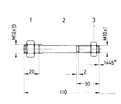
3 Screw threaded bolt (self-made) into crankshaft and counterlock with hex nut.
|
|||||
|
1 Hex nut M 12 x 1.5
2 Threaded bolt 10 mm dia
3 Hex nut M 10 x 1
|
|||||
|
|
|||||
|
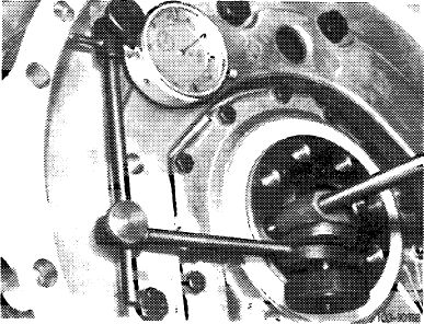
4 Attach dial gauge holder with dial gauge to threaded bolt.
5 Position feeler pin at fitting point of centering surface. Set dial gauge to 0.
|
 |
||||
|
|
|||||
|
01.2-220/2 F3
|
|||||
|
|
|||||
|
|
|||
|
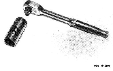
6 Rotate crankshaft for one full turn by means of tool combination. Vertical runout should not exceed max 0.10 mm.
Note: When rotating crankshaft, make sure that the feeler pin of the dial gauge is not getting stuck.
|
 |
||
|
|
|||
|
7 Correct vertical runout by light blows against intermediate flange.
8 Tighten fastening screws.
Note: If the vertical runout exceeds 0.10 mm, remove intermediate flange.
9 Increase diameter of both fitted bores in intermediate flange to 12.1 mm.
10 Repeat item 1-8.
|
|||
|
|
|||
|
01.2-220/3 F3
|
|||
|
|
|||