Knocking-out and inserting steel balls for main oil ducts
|
|
||||||||||||||||||||||||||||||||||||
|
01—130 Knocking-out and inserting steel balls for main oil ducts
|
||||||||||||||||||||||||||||||||||||
|
|
||||||||||||||||||||||||||||||||||||
|
Tightening torques
|
Nm
|
|||||||||||||||||||||||||||||||||||
|
|
||||||||||||||||||||||||||||||||||||
|
||||||||||||||||||||||||||||||||||||
|
|
||||||||||||||||||||||||||||||||||||
|
Necked-down screw for driven plate and flywheel
|
initial torque
|
40
|
||||||||||||||||||||||||||||||||||
|
torque angle
|
90°-100°
|
|||||||||||||||||||||||||||||||||||
|
|
||||||||||||||||||||||||||||||||||||
|
Note
|
 |
|||||||||||||||||||||||||||||||||||
|
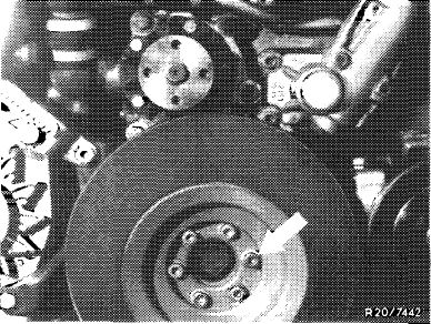
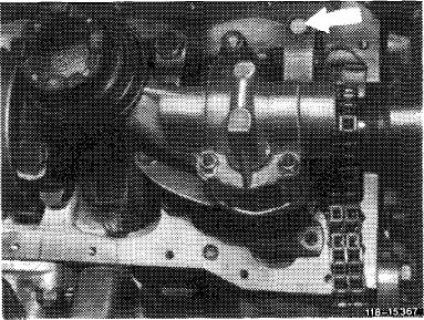
Since October 1976 the 2 main oil ducts (arrows) in cylinder crankcase at transmission end are closed by means of steel balls 15 mm dia. VO DIN 5401 part no. 005401 515001.
|
||||||||||||||||||||||||||||||||||||
|
|
||||||||||||||||||||||||||||||||||||
|
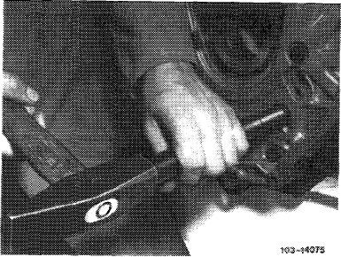
For cleaning main oil ducts during engine repairs, the steel balls must be knocked-out from direction of front end of engine.
Undamaged steel balls can be used several times without refinishing ball seat in crankcase.
Damaged and rusty steel balls should be replaced.
|
 |
|||||||||||||||||||||||||||||||||||
|
|
||||||||||||||||||||||||||||||||||||
|
01.2-130/1 F3
|
||||||||||||||||||||||||||||||||||||
|
|
||||||||||||||||||||||||||||||||||||
|
|
|||
|
Knocking-out steel ball in upper main oil duct
|
 |
||
|
1 Remove transmission.
|
|||
|
2 Remove flywheel (03-410).
|
|||
|
|
|||
|
3 Remove radiator (20-420).
|
 |
||
|
4 Remove vibration damper (03—340).
|
|||
|
|
|||
|
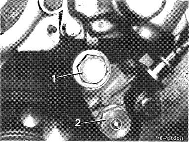
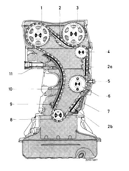
5 Unscrew closing plug (1) and screw oil pressure relief valve out of main oil duct.
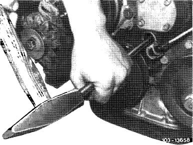
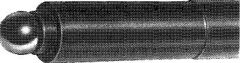
6 Knock-out steel ball from direction of engine front end by means of a round steel bar 13 mm dia. and approx. 700 mm long.
|
 |
||
|
|
|||
|
Knocking-out steel ball in lower main oil duct
|
 |
||
|
1 Remove transmission.
|
|||
|
2 Remove flywheel (03-410).
|
|||
|
|
|||
|
01.2-130/2 F3
|
|||
|
|
|||
|
|
|||
|
3 Remove radiator (20-420).
4 Remove vibration damper and compensating weight (03-340).
|
103-8363
|
||
|
|
|||
|
5 Remove complete oil pan (01—310).
6 Remove oil pump (18-210).
|
 |
||
|
|
|||
|
7 Remove slide rail (2b) in crankcase (05—340).
8 Knock-out steel ball from direction of engine front end by means of a round steel bar 13 mm dia. and approx. 700 mm long.
|
 |
||
|
|
|||
|
01.2-130/3 F3
|
|||
|
|
|||
|
|
||||
|
Closing main oil duct
|
||||
|
|
||||
|
1 Thoroughly clean ball seat and bore in main oil duct.
2 Coat up on self-made knocking-in mandrel with grease and place steel ball into cup.
|
 |
|||
|
|
||||
|
103-13 405
|
||||
|
|
||||
|
Material: C 45
|
 |
|||
|
|
||||
|
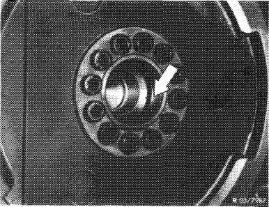
3 Position steel ball with knocking-in mandrel and knock-in up to stop on mandrel.
|
 |
|||
|
|
||||
|
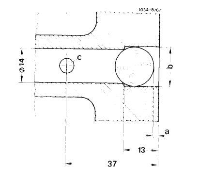
If the mandrel has no stop, do not exceed dimension a = max. 3 mm to prevent cracking of crankcase.
|
 |
|||
|
a = max. 3 mm
b= dia. 14.75 to 14.86 mm
c = oil ducts to crankshaft bearing
|
||||
|
01.2-130/4 F3
|
||||
|
|
||||
|
|
|||
|
4 Mount all parts taken off or removed.
5 Run engine warm and check for leaks.
Note: If oil flows out as the result of a leaking ball seat, knock-out respective steel ball and close main oil duct with a closing plug after cutting the required threads into duct.
|
|||
|
|
|||
|
Closing main oil duct with closing plug
|
|||
|
|
|||
|
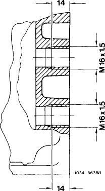
1 Cut threads M 16 x 1.5 mm approx. 14 mm deep into respective main oil duct.
2 Carefully clean main oil duct.
|
 |
||
|
3 Screw closing plug M 16 x 1.5 mm DIN 908, part no. 000 908 016 001 with aluminum sealing ring A 16 x 22 mm DIN 7603 – AL, part no. 007 603 016 102, and tighten to 40 Nm.
|
|||
|
|
|||
|
01.2-130/5 F3
|
|||
|
|
|||