Complete removal and installation of oil pan
|
|
|||||||||||||||||||||||||||||||||||||||||||||||||||
|
01-310 Complete removal and installation of oil pan
|
|||||||||||||||||||||||||||||||||||||||||||||||||||
|
|
|||||||||||||||||||||||||||||||||||||||||||||||||||
|
Oil capacity in liters
|
|||||||||||||||||||||||||||||||||||||||||||||||||||
|
|
|||||||||||||||||||||||||||||||||||||||||||||||||||
|
Oil dipstick color code
|
wine red, pink brown1)
|
yellow-green
|
|||||||||||||||||||||||||||||||||||||||||||||||||
|
|
|||||||||||||||||||||||||||||||||||||||||||||||||||
|
Oil pan
|
5.5
|
||||||||||||||||||||||||||||||||||||||||||||||||||
|
|
|||||||||||||||||||||||||||||||||||||||||||||||||||
|
Oil filter
|
0.5
|
||||||||||||||||||||||||||||||||||||||||||||||||||
|
|
|||||||||||||||||||||||||||||||||||||||||||||||||||
|
Model 107, 114, 116
|
0.7
|
||||||||||||||||||||||||||||||||||||||||||||||||||
|
|
|||||||||||||||||||||||||||||||||||||||||||||||||||
|
Air oil cooler
|
|||||||||||||||||||||||||||||||||||||||||||||||||||
|
|
|||||||||||||||||||||||||||||||||||||||||||||||||||
|
Model 123, 126
|
0.40
|
||||||||||||||||||||||||||||||||||||||||||||||||||
|
|
|||||||||||||||||||||||||||||||||||||||||||||||||||
|
l) (USA) model year 1975/76
|
|||||||||||||||||||||||||||||||||||||||||||||||||||
|
|
|||||||||||||||||||||||||||||||||||||||||||||||||||
|
Tightening torques
|
Nm
|
||||||||||||||||||||||||||||||||||||||||||||||||||
|
|
|||||||||||||||||||||||||||||||||||||||||||||||||||
|
|||||||||||||||||||||||||||||||||||||||||||||||||||
|
|
|||||||||||||||||||||||||||||||||||||||||||||||||||
|
Stud wrench 5 mm, 300 mm long
|
 |
116 589 02 07 00
|
|||||||||||||||||||||||||||||||||||||||||||||||||
|
Stud wrench 6 mm, 440 mm long
|
116 589 03 07 00
|
||||||||||||||||||||||||||||||||||||||||||||||||||
|
|
|||||||||||||||||||||||||||||||||||||||||||||||||||
|
Engine support
|
 |
107 589 02 61 00
|
|||||||||||||||||||||||||||||||||||||||||||||||||
|
|
|||||||||||||||||||||||||||||||||||||||||||||||||||
|
Knocking-in tool for oil dipstick guide tube
|
 |
117 589 00 31 00
|
|||||||||||||||||||||||||||||||||||||||||||||||||
|
|
|||||||||||||||||||||||||||||||||||||||||||||||||||
|
|||||||||||||||||||||||||||||||||||||||||||||||||||
|
|
|||||||||||||||||||||||||||||||||||||||||||||||||||
|
01.2-310/1 F3
|
|||||||||||||||||||||||||||||||||||||||||||||||||||
|
|
|||||||||||||||||||||||||||||||||||||||||||||||||||
|
|
|||||||||||||||||||||||||||||||||||||||||||||||||||||||||||||||||||||||||||||||||||||||||||||||||||
|
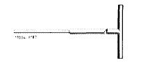
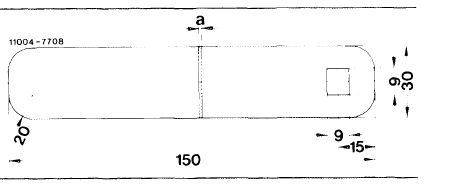
Self-made tools
|
|||||||||||||||||||||||||||||||||||||||||||||||||||||||||||||||||||||||||||||||||||||||||||||||||||
|
|
|||||||||||||||||||||||||||||||||||||||||||||||||||||||||||||||||||||||||||||||||||||||||||||||||||
|
Gauges for cutting-off radial sealing rings
Radial sealing ring graphite-grey
Part no. 000 997 65 41 a=1mm
Radial sealing ring yellow-brown a = 0.5 mm
|
 |
||||||||||||||||||||||||||||||||||||||||||||||||||||||||||||||||||||||||||||||||||||||||||||||||||
|
|
|||||||||||||||||||||||||||||||||||||||||||||||||||||||||||||||||||||||||||||||||||||||||||||||||||
|
Note
|
|||||||||||||||||||||||||||||||||||||||||||||||||||||||||||||||||||||||||||||||||||||||||||||||||||
|
|
|||||||||||||||||||||||||||||||||||||||||||||||||||||||||||||||||||||||||||||||||||||||||||||||||||
|
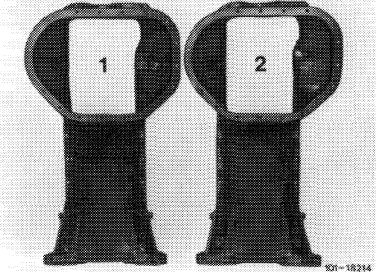
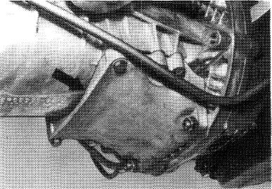
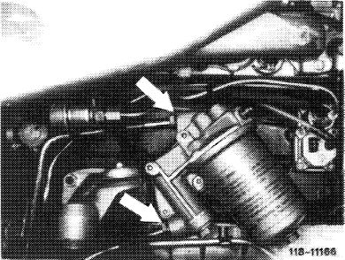
The modified oil pan (1) is installed on models 107, 116 and 123 since October 1979 and model 126 since begin of series.
For this purpose, the rear 3 fastening threads on cylinder crankcase have been changed on both sides from M 6 to M 8 mm.
Begin of series: October 1979
|
 |
||||||||||||||||||||||||||||||||||||||||||||||||||||||||||||||||||||||||||||||||||||||||||||||||||
|
|||||||||||||||||||||||||||||||||||||||||||||||||||||||||||||||||||||||||||||||||||||||||||||||||||
|
|
|||||||||||||||||||||||||||||||||||||||||||||||||||||||||||||||||||||||||||||||||||||||||||||||||||
|
This modified oil pan is screwed to cylinder crankcase at the rear with 6 screws M 8 x 95 mm, formerly 4 screws M 6 x 40 mm and 2 screws M 6 x 25 mm.
|
|||||||||||||||||||||||||||||||||||||||||||||||||||||||||||||||||||||||||||||||||||||||||||||||||||
|
|
|||||||||||||||||||||||||||||||||||||||||||||||||||||||||||||||||||||||||||||||||||||||||||||||||||
|
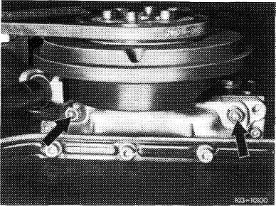
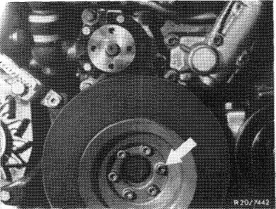
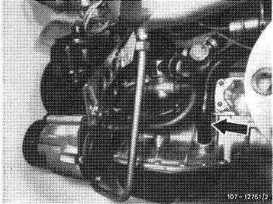
On model 126 the modified oil pan is screwed to cylinder crankcase together with supporting tray (arrow) by means of 6 screws M 8 x 110 mm.
|
 |
||||||||||||||||||||||||||||||||||||||||||||||||||||||||||||||||||||||||||||||||||||||||||||||||||
|
|
|||||||||||||||||||||||||||||||||||||||||||||||||||||||||||||||||||||||||||||||||||||||||||||||||||
|
01.2-310/2 F3
|
|||||||||||||||||||||||||||||||||||||||||||||||||||||||||||||||||||||||||||||||||||||||||||||||||||
|
|
|||||||||||||||||||||||||||||||||||||||||||||||||||||||||||||||||||||||||||||||||||||||||||||||||||
|
|
|||
|
If a modified oil pan is installed in the course of repairs, the respective threaded bores in cylinder crankcase should be enlarged from M 6 to M 8 mm.
|
|||
|
|
|||
|
In the event of repairs, use radial sealing ring 000 997 90 41 (yellow-brown) with a projection of 0.5 mm on both sides, except when a new or newly ground crankshaft with new crankshaft bearings is installed. In such a case, use radial sealing ring
000 997 69 41 (graphite-grey) with a projection of
1 mm on both sides. This will protect the rear bearing journal of crankshaft against being overheated under influence of a low crankshaft bearing play and excessive pressure against yellow-brown radial sealing ring.
|
|||
|
|
|||
|
Removal
|
|||
|
|
|||
|
Model 107
1 Remove front axle (33-100).
2 Detach oil return pipe at cylinder head and pull off at oil pan.
3 Detach oil dipstick guide tube at cylinder head.
4 Detach steering rod at one side.
|
|||
|
|
|||
|
5 Detach alternator holder strut at oil pan.
6 Remove oil pan downward.
Note: Hold engine with engine support when working underneath engine.
|
 |
||
|
|
|||
|
01.2-310/3 F3
|
|||
|
|
|||
|
|
|||
|
Model 114
|
|||
|
|
|||
|
1 Remove front axle (33-100).
|
|||
|
|
|||
|
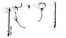
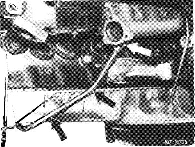
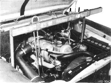
2 Remove exhaust gas recirculation line (arrows) for USA models.
|
 |
||
|
|
|||
|
3 Remove oil lines for automatic transmission.
4 Detach oil dipstick guide tube at cylinder head.
5 Pull oil return line (1) off of oil pan (18-030).
6 Drain engine oil.
7 Remove oil pan.
Note: Hold engine with engine support while working underneath engine.
|
 |
||
|
|
|||
|
Model 116
|
 |
||
|
1 Remove radiator.
|
|||
|
2 Remove vibration damper (03—340).
|
|||
|
|
|||
|
01.2-310/4 F3
|
|||
|
|
|||
|
|
|||
|
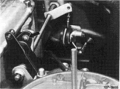
3 Detach control shaft (07.2-442).
|
 |
||
|
|
|||
|
4 Detach both front engine mounts and engine dampers.
5 Pull oil return line off of oil pan (18-030).
6 Drain engine oil.
|
 |
||
|
|
|||
|
1 Remove oil pan lower section and oil pump. Remove fuel pump of carburetor engines.
8 Remove oil lines for automatic transmission.
9 Detach oil dipstick guide tube at cylinder head and drive it out from below with a 7.5 mm dia. mandrel.
Knock-out oil guide tube for drawing off oil with knocking-out mandrel 9 mm.
|
 |
||
|
USA version
|
|||
|
|
|||
|
10 Detach rear engine mount, lift engine and place an approximately 40 mm thick piece of wood underneath.
11 Lift front of engine and place approximately 60 mm thick pieces of wood on both sides between the engine carrier and engine mounts.
12 Detach oil pan and remove forward.
|
|||
|
|
|||
|
01.2-310/5 F3
|
|||
|
|
|||
|
|
||||
|
Model 123
|
 |
|||
|
1 Remove engine (01—030).
|
||||
|
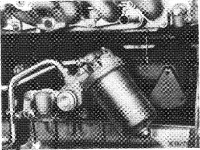
2 Remove oil filter complete with lines.
|
||||
|
|
||||
|
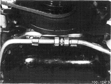
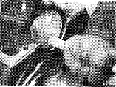
3 Pull-off oil return pipe (arrow).
|
 |
|||
|
4 Loosen strut for alternator bracket on oil pan.
|
||||
|
5 Remove oil pan.
|
||||
|
USA version
|
||||
|
|
||||
|
Model 126
|
||||
|
|
||||
|
1 Pull-off oil return line on oil pan.
|
||||
|
|
||||
|
2 Remove supporting tray.
|
||||
|
|
||||
|
3 Turn wheels completely to the left.
|
||||
|
|
||||
|
4 Unscrew cover plate.
|
||||
|
|
||||
|
5 Remove vibration damper (03—340).
|
||||
|
|
||||
|
6 Unscrew lower holding bracket of alternator.
|
||||
|
|
||||
|
01.2-310/6 F3
|
||||
|
|
||||
|
|
||
|
7 Unscrew oil pan upper half to the extent that it is still held to crankcase by 2 screws.
8 Remove oil pan lower half.
9 Remove oil pump (3 screws).
|
||
|
|
||
|
10 Pull oil dipstick guide tube at top out of holder and knock out of oil pan upper half from below
by means of a plastic hammer.
11 On vehicles with refrigerant compressor, remove lower strut.
|
||
|
|
||
|
12 Disconnect regulating linkage.
13 Unflange propeller shaft at transmission and push back.
|
||
|
|
||
|
14 Unscrew engine shock absorber below.
15 Unscrew screws for engine carrier on engine mount.
16 Suspend engine at the front and rear on engine removing eyes and lift until oil pan can be removed.
|
||
|
|
||
|
01.2-310/7 F3
|
||
|
|
||
|
|
||||
|
Installation, all models
|
 |
|||
|
1 Clean parting surface on cylinder crankcase and oil pan.
2 Renew rear radial sealing ring in oil pan and work in.
|
||||
|
Note: Do not install radial sealing ring 000 997 90 41 (yellow-brown) in engines which are provided with a new or refinished crankshaft and new crankshaft bearings in the event of repairs.
|
||||
|
|
||||
|
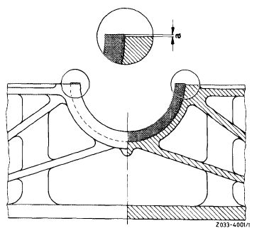
3 To arrive at an overlap, cut off radial sealing ring approx. 0.5 or 1.0 mm above parting surface. Use self-made gauge for this purpose.
|
 |
|||
|
Radial sealing ring, part no.
|
Dimension a (mm)
|
|||
|
000 997 69 41 (graphite-grey) 000 997 90 41 (yellow-brown)
|
1.0 0.5
|
|||
|
4 Provide radial sealing ring with engine oil.
5 Coat parting surface of oil pan with sealing compound.
6 Install oil pan and screw-on lightly at front and rear with 2 screws each.
Attention!
The oil pan should rest against or be screwed to intermediate flange prior to tightening fastening screws for crankcase.
7 For further installation proceed vice versa.
Attention!
Check regulating linkage for function.
|
||||
|
|
||||
|
0.1.2-310/8 F3
|
||||
|
|
||||