Checking decel shutoff
|
|
||
|
07.3-140 Checking decel shutoff
|
||
|
|
||
|
Test values
|
||
|
|
||
|
Speed Engine speed 1/min
km/h without refrigerant with refrigerant
compressor compressor
>35 > 1100 >1300
Conventional tools
Revolution counter, volt-ohmmeter
Digital multimeter with means for measuring AC (for impulse transmitter test)
|
||
|
|
||
|
Note
|
||
|
|
||
|
Since decel shutoff requires engine speed impulses and driving speeds, the respective component can be tested only on a dynamometer or on the road.
A function test of impulse transmitter can also be made by means of workshop oscilloscope Bosch MOT 300/ 400, 202 and SUN 1080, 1019, 2110 in position „Primary, special „or „Generator test”.
|
||
|
|
||
|
Testing on dynamometer
|
||
|
|
||
|
Remove air cleaner.
Run on dynamometer at approx. 70 km/h in 4th speed or driving position „D”. Release accelerator pedal, air flow sensor plate will move into zero position. As soon as combustion starts again at approx. 1100/min or approx. 1300/min with refrigerant compressor, the air flow sensor plate will move into idle position. Check decel shutoff valve and its activation, if required.
|
||
|
|
||
|
Testing without dynamometer (road test)
Run engine at idle.
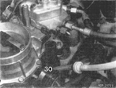
Test decel shutoff valve (30).
Test activation of switchover valve (43a).
Test speed-dependent control.
07.3.2 I la—140/1 F2
|
||
|
|
||
|
|
|||
|
Testing
|
 |
||
|
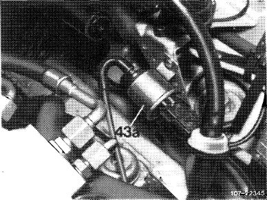
Testing decel shutoff valve (30)
1 Run engine at idle. Pull off vacuum lines on switch
over valve (43a) and connect with each other. Decel
shutoff valve (30) will then open and the engine should
stop.
If engine keeps running, check vacuum lines. Intake
manifold vacuum should be available at idle. If vacuum
is available, replace decel shutoff valve (30).
|
|||
|
|
|||
|
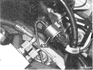
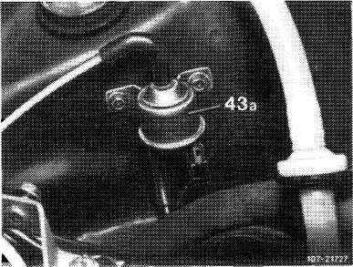
Layout switchover valves (43a)
|
 |
||
|
Model 107
|
|||
|
|
|||
|
Model 123
|
 |
||
|
|
|||
|
Model 126
43 Switchover valve air conditioning
(identification: green cap) 43a Switchover valve decel shutoff
(identification: gray cap)
|
 |
||
|
|
|||
|
07.3.2 I la—140/2 F2
|
|||
|
|
|||
|
|
||||
|
Checking activation of switchover valve
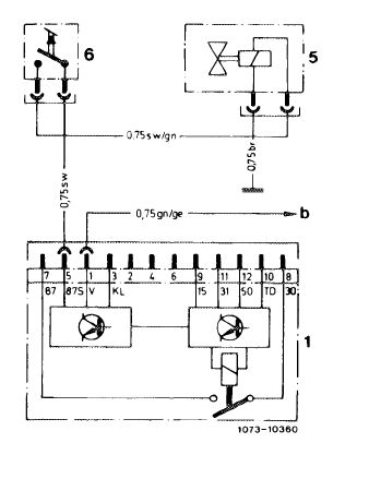
2 Pull off fuel pump relay. Bridge jack 7 (terminal 87) and 8 (terminal 30), so that fuel pump will run. Start engine, connect jack 5 (terminal 87 S) of coupler with battery voltage. Engine should now stop.
If engine does not stop, check microswitch (3 or 6) or switchover valve (43a or 5).
|
 |
|||
|
|
||||
|
1 Electronic fuel pump relay
5 Switchover valve
6 Microswitch
b Tachometer transmitter
|
 |
|||
|
|
||||
|
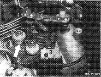
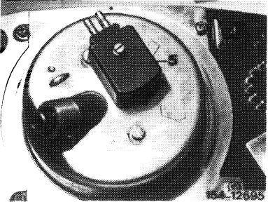
Testing microswitch (3)
Pull off coupler on microswitch. Connect ohmmeter.
Readout: At idle 0 £2
When accelerating °° £2.
Check adjustment of slotted lever, if required. Roller in slotted lever should rest free of tension against final stop. Check rotary spring (arrow), if required.
|
 |
|||
|
|
||||
|
07.3.2 lla—140/3
|
F2
|
|||
|
|
||||
|
|
||||
|
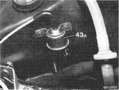
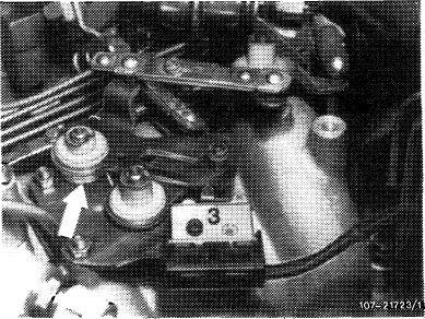
Testing switchover valve (43a)
Pull coupler from microswitch (3) and connect cable, color black/green, to battery voltage, engine should now stop. If engine does not stop, test line with an ohmmeter for passage or replace switchover valve (43a).
|
 |
|||
|
|
||||
|
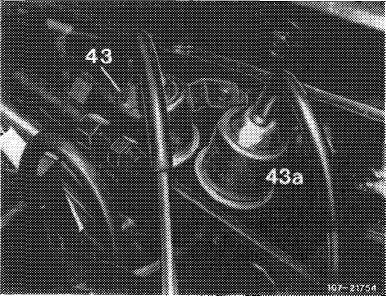
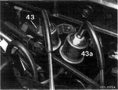
Layout switchover valves (43a)
|
 |
|||
|
Model 107
|
||||
|
|
||||
|
Model 123
|
 |
|||
|
|
||||
|
Model 126
43 Switchover valve air conditioning
(identifiaction: green cap) 43a Switchover valve decel shutoff
(identifiaction: gray cap)
|
 |
|||
|
|
||||
|
07.3.2 I la —140/4
|
F 2
|
|||
|
|
||||
|
|
||||
|
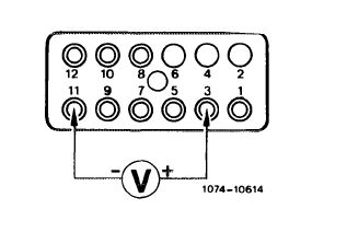
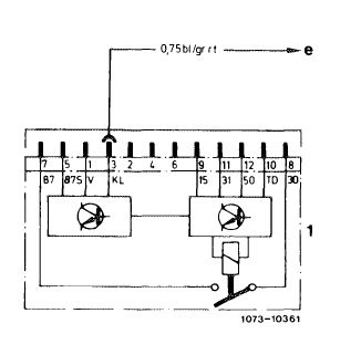
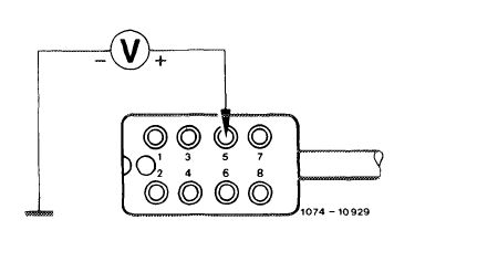
3 Check cutting-in impulse of refrigerant compressor. For this purpose, run engine at idle. Connect positive cable (red) of voltmeter to jack 3 (terminal KL) and negative cable (black) to jack 11 (terminal 31).
When switching-on refrigerant compressor, battery voltage should be available.
If no voltage is available, test line blue/gray/red (terminal KL) to refrigerant compressor for interruption.
|
 |
|||
|
|
||||
|
Note: With air-conditioning system switched on, voltage should be available at jack 3 (terminal KL) of fuel pump relay (refer to wiring diagram group 83 air-conditioning system).
|
 |
|||
|
1 Fuel pump relay
e Refrigerant compressor
|
||||
|
|
||||
|
Test speed-dependent control
4 Pull coupler from switchover valve (43a) and connect voltmeter to coupler. Operate on dynamometer or on road in 4th gear, or in driving position „D” at 70 km/h. Release accelerator pedal, battery voltage should be available. If there is no voltage, test impulse transmitter on tachometer or replace fuel pump relay, if required.
There should be no voltage below approx. 1100/min or approx. 1300/min with refrigerant compressor.
|
||||
|
|
||||
|
Testing impulse transmitter on tachometer
5 A prerequisite for a signal is that the speed indicator is operational.
Test impulses for decel shutoff. Pull off fuel pump relay for this purpose.
|
 |
|||
|
|
||||
|
07.3.2 lla-140/5
|
F 2
|
|||
|
|
||||
|
|
||||
|
Electronic tachometer
|
||||
|
|
||||
|
a) Testing output signal
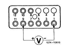
Connect digital multimeter (position V = DC). For this purpose, connect positive cable (red) to jack 9 (terminal 15), grounding cable (black) to jack 1 (terminal V).
Attention!
Perform measurements in position V = only. Wrong handling will damage tachometer electronics.
|
 |
|||
|
|
||||
|
Bridge jack 7 (terminal 87) and jack 8 (terminal 30), fuel pump will then run.
Operate on dynamometer or on road in 4th gear or in driving position „D” at 70 km/h. Readout should indicate ^ 1 Volt DC (in position V =). Measuring value increases with increasing vehicle speed.
|
 |
|||
|
|
||||
|
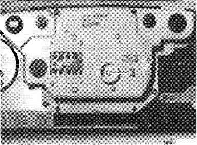
If there is no readout, test cable from jack 1 (terminal V) to impulse transmitter connection (3) by means of an ohmmeter for passage.
|
iff if.
|
|||
|
Model 107, 126
3 Impulse transmitter connection
|
||||
|
|
||||
|
Test speed readout of tachometer.
If there is no readout, remove instrument cluster. Remove 8-pole plug on tachometer.
|
 |
|||
|
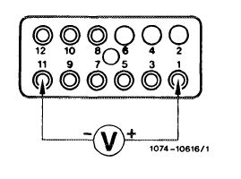
b) Testing input signal
Connect digital multimeter with means for measuring AC (in position V ~ or V -^ ) to jack 5.
Red = positive (jack 5) Black = vehicle ground
|
||||
|
|
||||
|
07.3.2 I la—140/6
|
F 2
|
|||
|
|
||||
|
|
|||
|
Operate on dynamometer or on road in 4th gear or in driving position „D” at 70 km/h. Readout ^ should amount to 1 Volt AC (in position V ~). Measuring value increases with increasing driving speed.
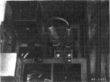
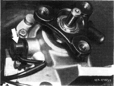
If there is no readout, test cable for passage by means of an ohmmeter or replace cable or impulse transmitter (arrow) in transmission.
|
 |
||
|
Impulse transmitter automatic transmission
|
|||
|
|
|||
|
Mechanical tachomater
Connect digital multimeter with means for measuring AC (in position V ~or”v„). For this purpose, connect position cable (red) to jack 1 (terminal V), grounding cable (black) to jack 11 (terminal 31).
Bridge jack 7 (terminal 87) and jack 8 (terminal 30), fuel pump will now run.
Operate on dynamometer or on road in 4th gear or in driving position „D” at approx. 70 km/h. Readout ^should amount to 1 Volt AC (in position V ~ ). Measuring value increases with increasing vehicle speed, speed.
If there is no readout, test cable for passage by means of an ohmmeter. Replace cable or impulse transmitter (5) on tachometer, if required.
|
 |
||
|
|
|||
|
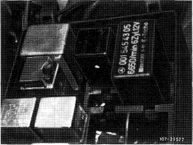
Test resistance of impulse transmitter (5). Nominal = 650- 1370 J2.
If the nominal value is exceeded or not attained, replace impulse transmitter.
|
 |
||
|
Model 123
5 Impulse transmitter
|
|||
|
|
|||
|
07.3.2 Ma—140/7 F2
|
|||
|
|
|||
|
|
||||
 |
||||
|
|
||||
|
1073-10369
|
||||
|
|
||||
|
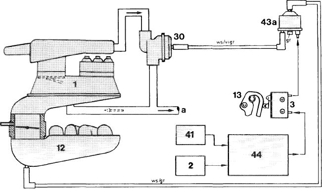
Function diagram decel shutoff
1 Mixture controller
2 Transistorized switching unit
3 Microswitch
1 2 Intake manifold
13 Slotted lever
30 Decel shutoff valve
|
41 Impulse transmitter mechanical
tachometer 43a Switchover valve
decelshutoff 44 Fuel pump relay a To idle speed air distributor
|
Color code gr =gray vi = purple ws = white
|
||
|
|
||||
|
Note: For operation of decel shutoff and idle speed stabilization refer to 07.3—500.
|
||||
|
|
||||
|
07.3.2 lla-140/$ F2
|
||||
|
|
||||
|
|
|||||
 |
|||||
|
|
|||||
|
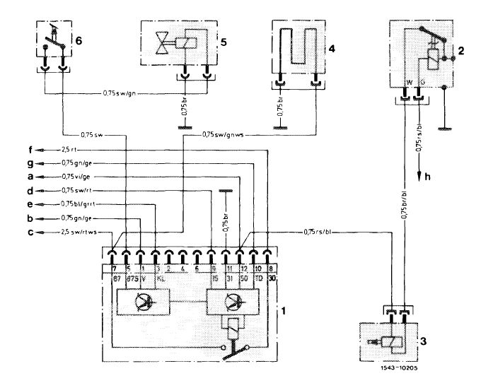
Wiring diagram decel shutoff model 1 23
|
|||||
|
|
|||||
|
1 Fuel pump relay
2 Thermo time switch
3 Cold starting valve
4 Warm-up compensator
5 Switchover valve
6 Microswitch
|
a To output starter lockout and backup lamp switch
b Transmitter mechanical tachometer
c Fuel pump
d Fuse 1 2 terminal 15 access
e Refrigerant compressor
f Cable connector engine terminal 30
g Cable connector terminal TD
h Cable connector engine terminal 50
|
Color code bl =blue br = brown
|
|||
|
ge gn
gr rs rt
|
= yellow = green = gray = pink = red
|
||||
|
|
|||||
|
sw = black vi = purple ws = white
|
|||||
|
|
|||||
|
07.3.2 lla-140/9 F2
|
|||||
|
|
|||||
|
|
|||||||||||||||||||||||||||||||||||||||||||||||||||||||
 |
|||||||||||||||||||||||||||||||||||||||||||||||||||||||
|
|
|||||||||||||||||||||||||||||||||||||||||||||||||||||||
|
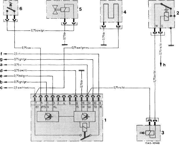
Wiring diagram decel shutoff
1 Fuel pump relay
2 Thermo time switch
3 Cold starting valve
4 Warm-up compensator
5 Switchover valve
6 Microswitch
|
model 107, 126
|
||||||||||||||||||||||||||||||||||||||||||||||||||||||
|
a Cable connector engine terminal 50
b Transmitter electronic tachometer
c Fuel pump
d Fuse 14 terminal 1 5 access
e Refrigerant compressor
f Cable connector terminal 30
g Cable connector terminal TD
h Cable connector engine terminal 50
|
|
||||||||||||||||||||||||||||||||||||||||||||||||||||||
|
|
|||||||||||||||||||||||||||||||||||||||||||||||||||||||
|
07.3.2 Ma—140/10
|
F 2
|
||||||||||||||||||||||||||||||||||||||||||||||||||||||
|
|
|||||||||||||||||||||||||||||||||||||||||||||||||||||||
|
|
|||||||||||||||||||||||||||||||||||||||||||||||||||||||||||||||||||||||||||||||
 |
|||||||||||||||||||||||||||||||||||||||||||||||||||||||||||||||||||||||||||||||
|
|
|||||||||||||||||||||||||||||||||||||||||||||||||||||||||||||||||||||||||||||||
|
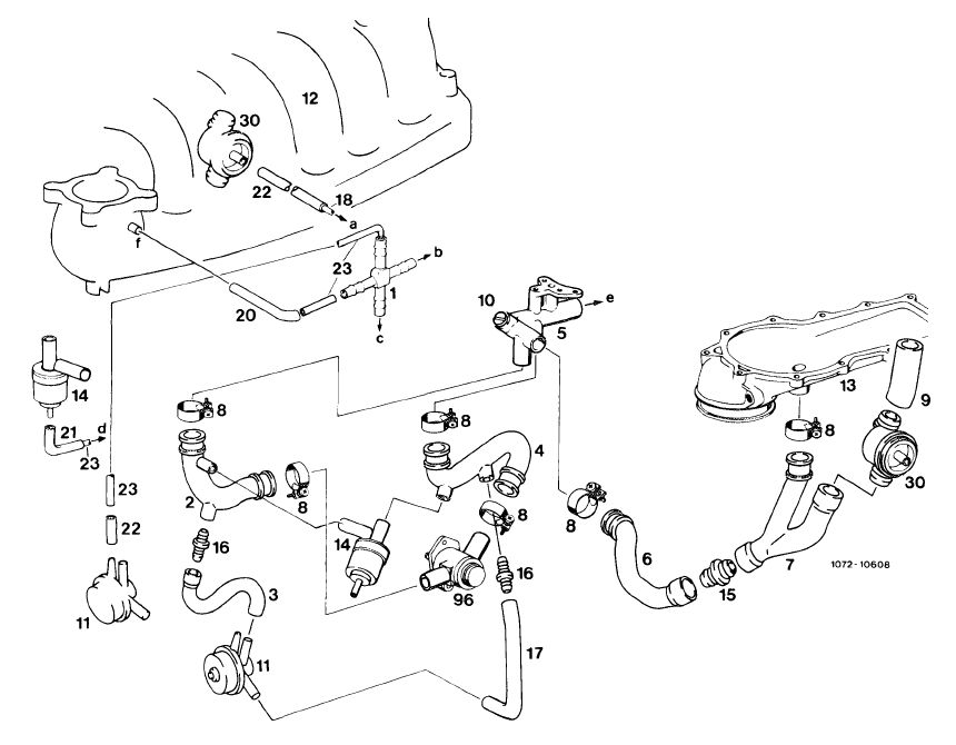
Decel shutoff and idle speed stabilization
|
|||||||||||||||||||||||||||||||||||||||||||||||||||||||||||||||||||||||||||||||
|
|
|||||||||||||||||||||||||||||||||||||||||||||||||||||||||||||||||||||||||||||||
|
To switchover valve decel shutoff To switchover valve decel shutoff To switchover valve air conditioning To switchover valve air conditioning Connection idle speed air Vacuum connection intake manifold
|
||||||||||||||||||||||||||||||||||||||||||||||||||||||||||||||||||||||||||||||
|
|
|||||||||||||||||||||||||||||||||||||||||||||||||||||||||||||||||||||||||||||||
|
07.3.2 lla-140/11
|
F 2
|
||||||||||||||||||||||||||||||||||||||||||||||||||||||||||||||||||||||||||||||
|
|
|||||||||||||||||||||||||||||||||||||||||||||||||||||||||||||||||||||||||||||||