Statically balancing of flywheel
|
|
||||||||||||||||||||||||||||||||||||||||
|
03-440 Statically balancing of flywheel
|
||||||||||||||||||||||||||||||||||||||||
|
|
||||||||||||||||||||||||||||||||||||||||
|
||||||||||||||||||||||||||||||||||||||||
|
|
||||||||||||||||||||||||||||||||||||||||
|
Balancing mandrel (Flywheel for automatic and manual transmission)
|
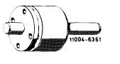 |
617 589 00 63 00
|
||||||||||||||||||||||||||||||||||||||
|
|
||||||||||||||||||||||||||||||||||||||||
|
Conventional tool
|
||||||||||||||||||||||||||||||||||||||||
|
|
||||||||||||||||||||||||||||||||||||||||
|
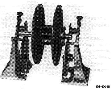
Rotating device for static balancing
|
e.g. made by Trebel, D-4030 Ratingen type EO
|
|||||||||||||||||||||||||||||||||||||||
|
|
||||||||||||||||||||||||||||||||||||||||
|
Note
|
||||||||||||||||||||||||||||||||||||||||
|
|
||||||||||||||||||||||||||||||||||||||||
|
The engine is fully balanced, that is, the complete engine has been balanced on a balancing machine.
Since in the event of repairs this type of balancing cannot be performed, while on the other hand the balanced condition of the engine should be maintained as much as possible, a new flywheel must be brought to the same balancing condition as the removed flywheel.
|
||||||||||||||||||||||||||||||||||||||||
|
|
||||||||||||||||||||||||||||||||||||||||
|
Static balancing
|
||||||||||||||||||||||||||||||||||||||||
|
|
||||||||||||||||||||||||||||||||||||||||
|
1 Place old and new flywheel one above the other in such a manner that all the bores are in alignment and both coupling surfaces are facing in one direction.
|
||||||||||||||||||||||||||||||||||||||||
|
|
||||||||||||||||||||||||||||||||||||||||
|
03.8-440/1
|
||||||||||||||||||||||||||||||||||||||||
|
|
||||||||||||||||||||||||||||||||||||||||
|
|
|||
|
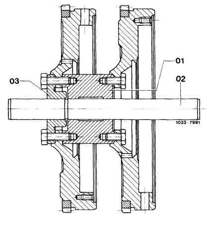
2 Insert balancing mandrel and screw-on new flywheel offset by accurately 180° in relation to old flywheel.
|
 |
||
|
01 Mounting
02 Shaft
03 Centering disc
|
|||
|
|
|||
|
3 Permit balancing mandrel with both flywheels to swing on rotating device to stop.
|
 |
||
|
|
|||
|
4 If an unbalance if found, drill as many holes on heavy side of new flywheel as required until the flywheels will come to a rest in any position without swinging.
Attention!
The hole circle dia., the drill dia. and the max. drilling depth must be maintained.
|
|||
|
|
|||
|
03.8-440/2
|
|||
|
|
|||