Removal and installation of cylinder head
|
|
|||||||||||||||||||||||||||||||||||||||||||||||||||||||||||
|
01—415 Removal and installation of cylinder head
|
|||||||||||||||||||||||||||||||||||||||||||||||||||||||||||
|
|
|||||||||||||||||||||||||||||||||||||||||||||||||||||||||||
|
Timing at 2 mm valve lift
|
Engine 110 Engine 110 Engine 110
California 1974 Federal
1973 and 1974
|
||||||||||||||||||||||||||||||||||||||||||||||||||||||||||
|
|
|||||||||||||||||||||||||||||||||||||||||||||||||||||||||||
|
Exhaust
|
24,57,71,78 24
|
30,95
|
|||||||||||||||||||||||||||||||||||||||||||||||||||||||||
|
Camshaft code number
|
|||||||||||||||||||||||||||||||||||||||||||||||||||||||||||
|
|
|||||||||||||||||||||||||||||||||||||||||||||||||||||||||||
|
Intake
|
25. 67. 74
|
25, 74
|
33, 91
|
||||||||||||||||||||||||||||||||||||||||||||||||||||||||
|
|
|||||||||||||||||||||||||||||||||||||||||||||||||||||||||||
|
opens after TDC
|
7°
|
11°
|
|||||||||||||||||||||||||||||||||||||||||||||||||||||||||
|
|
|||||||||||||||||||||||||||||||||||||||||||||||||||||||||||
|
Intake valve
|
|||||||||||||||||||||||||||||||||||||||||||||||||||||||||||
|
|
|||||||||||||||||||||||||||||||||||||||||||||||||||||||||||
|
closes after BDC
|
21
|
o
|
15°
|
||||||||||||||||||||||||||||||||||||||||||||||||||||||||
|
|
|||||||||||||||||||||||||||||||||||||||||||||||||||||||||||
|
Exhaust valve
|
opens before BDC
|
30°
|
22°
|
||||||||||||||||||||||||||||||||||||||||||||||||||||||||
|
|
|||||||||||||||||||||||||||||||||||||||||||||||||||||||||||
|
closes before TDC
|
|||||||||||||||||||||||||||||||||||||||||||||||||||||||||||
|
|
|||||||||||||||||||||||||||||||||||||||||||||||||||||||||||
|
) The camshaft code number is punched into rear end of camshaft.
|
|||||||||||||||||||||||||||||||||||||||||||||||||||||||||||
|
|
|||||||||||||||||||||||||||||||||||||||||||||||||||||||||||
|
|||||||||||||||||||||||||||||||||||||||||||||||||||||||||||
|
|
|||||||||||||||||||||||||||||||||||||||||||||||||||||||||||
|
1 ) 0.05 mm larger during lasting outside temperatures below —20°C.
|
|||||||||||||||||||||||||||||||||||||||||||||||||||||||||||
|
|
|||||||||||||||||||||||||||||||||||||||||||||||||||||||||||
|
Tightening torques
|
Nm
|
||||||||||||||||||||||||||||||||||||||||||||||||||||||||||
|
|
|||||||||||||||||||||||||||||||||||||||||||||||||||||||||||
|
Bolts and cap nuts for cylinder head cover
|
|||||||||||||||||||||||||||||||||||||||||||||||||||||||||||
|
|
|||||||||||||||||||||||||||||||||||||||||||||||||||||||||||
|
Necked-down screw for camshaft sprockets
|
80
|
||||||||||||||||||||||||||||||||||||||||||||||||||||||||||
|
|
|||||||||||||||||||||||||||||||||||||||||||||||||||||||||||
|
step 1
|
40
|
||||||||||||||||||||||||||||||||||||||||||||||||||||||||||
|
|
|||||||||||||||||||||||||||||||||||||||||||||||||||||||||||
|
Cylinder head bolts M 12 x 1.5 on cold engine
|
|||||||||||||||||||||||||||||||||||||||||||||||||||||||||||
|
|
|||||||||||||||||||||||||||||||||||||||||||||||||||||||||||
|
step 2
|
70
|
||||||||||||||||||||||||||||||||||||||||||||||||||||||||||
|
|
|||||||||||||||||||||||||||||||||||||||||||||||||||||||||||
|
|||||||||||||||||||||||||||||||||||||||||||||||||||||||||||
|
|
|||||||||||||||||||||||||||||||||||||||||||||||||||||||||||
|
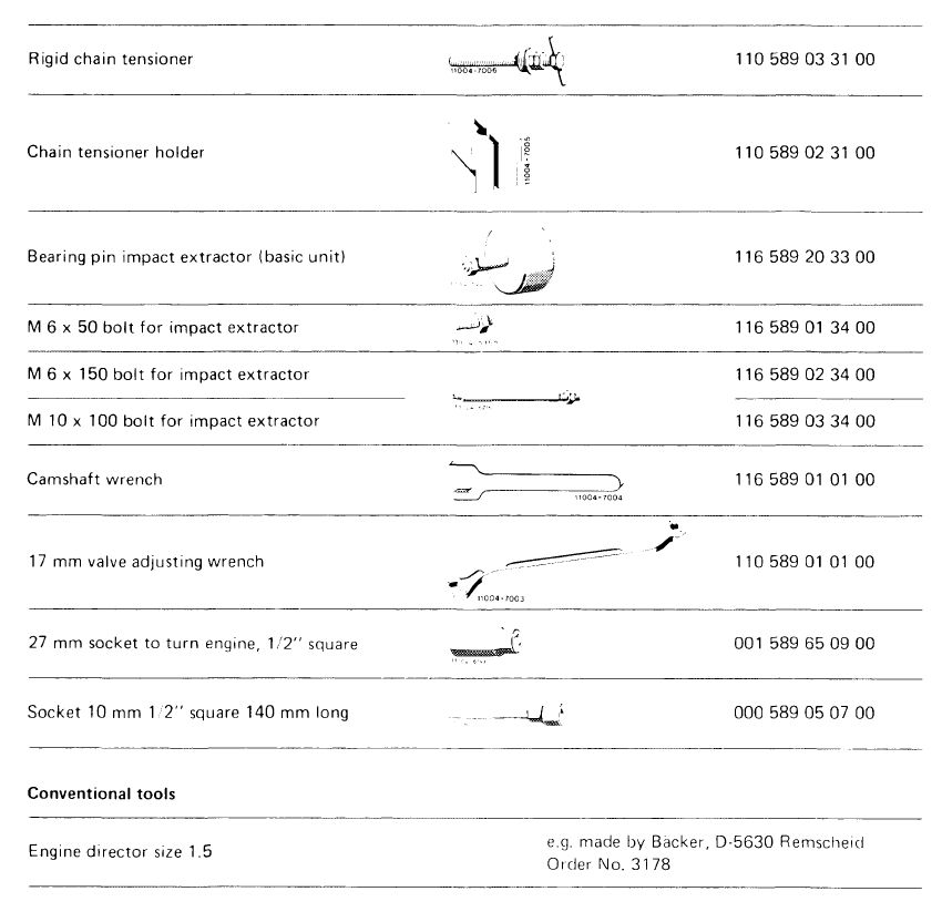
Remover and installer for rocker arm
|
 |
110 589 04 61 00
|
|||||||||||||||||||||||||||||||||||||||||||||||||||||||||
|
|
|||||||||||||||||||||||||||||||||||||||||||||||||||||||||||
|
01.2-415/1 F3
|
|||||||||||||||||||||||||||||||||||||||||||||||||||||||||||
|
|
|||||||||||||||||||||||||||||||||||||||||||||||||||||||||||
|
|
||
 |
||
|
|
||
|
Note
|
||
|
|
||
|
A cylinder head may only be removed after the engine is cold. Removal is together with the camshaft housing, exhaust manifold and intake manifold.
|
||
|
|
||
|
01.2-415/2 F3
|
||
|
|
||
|
|
||||||||||||||||||||||||||||||||
|
There is only one type of cylinder head as a replacement part for carburetor and fuel injection engines.
If the cylinder head is used on a carburetor engine, the fuel injector bores must be plugged with 6 covers, part number 000 443 01 80 00.
Starting April 1978 exhaust valve seat rings 42 mm OD and valve guides 9 mm ID are installed in cylinder head. Exception: engines national version.
|
 |
|||||||||||||||||||||||||||||||
|
|
||||||||||||||||||||||||||||||||
|
Cylinder heads for engines with air injection are attached to exhaust ducts by means of threaded bores for air injection.
The diameter of the combustion chamber frame on cylinder head gaskets for the various repair stages varies:
|
 |
|||||||||||||||||||||||||||||||
|
||||||||||||||||||||||||||||||||
 |
||||||||||||||||||||||||||||||||
|
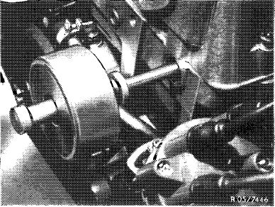
1 Remove compressor of models with an air conditioner.
|
||||||||||||||||||||||||||||||||
|
|
||||||||||||||||||||||||||||||||
|
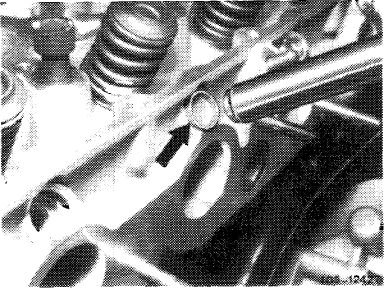
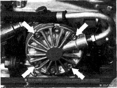
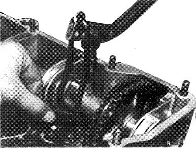
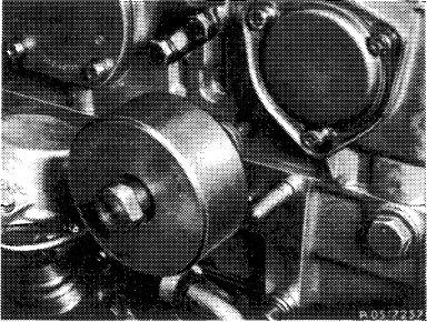
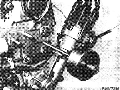
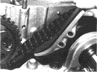
2 Remove oil pump of models with a level control system and place it to one side without undoing the lines. Only unscrew the bolts marked with an arrow for this purpose.
|
 |
|||||||||||||||||||||||||||||||
|
|
||||||||||||||||||||||||||||||||
|
01.2-415/3 F3
|
||||||||||||||||||||||||||||||||
|
|
||||||||||||||||||||||||||||||||
|
|
|||
|
3 Remove vacuum pump of models for USA.
|
 |
||
|
|
|||
|
4 Drain coolant from radiator and engine.
|
 |
||
|
Model 123
|
|||
|
|
|||
|
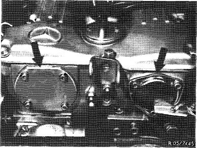
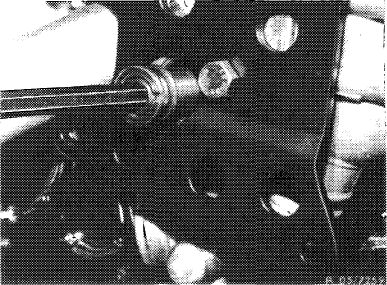
5 Unscrew both covers at front of camshaft housing.
|
 |
||
|
|
|||
|
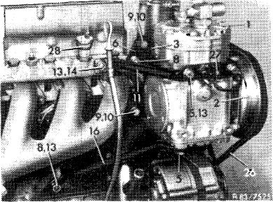
6 Disconnect all electric wires, heater water, fuel and vacuum lines which are connected to the cylinder head and intake manifold or carburetor.
|
|||
|
|
|||
|
01.2-415/4 F3
|
|||
|
|
|||
|
|
|||
|
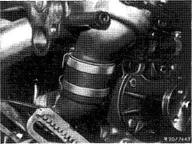
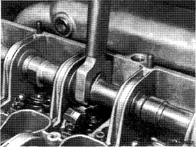
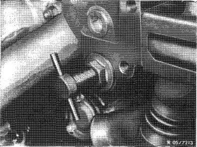
7 Remove longitudinal regulating shaft (3).
|
 |
||
|
|
|||
|
8 Disconnect oil return pipe at cylinder head.
|
 |
||
|
|
|||
|
9 Remove hose between thermostat housing and water pump.
Disconnect bypass line at water pump.
|
 |
||
|
|
|||
|
10 Disconnect oil dipstick guide tube from clamp on cylinder head and bend to one side.
|
|||
|
|
|||
|
01.2-415/5 F3
|
|||
|
|
|||
|
|
|||
|
11 Detach exhaust pipe at exhaust manifold and transmission. Unscrew pre-heating cowl of models with carburetor engines.
|
|||
|
|
|||
|
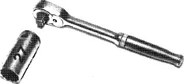
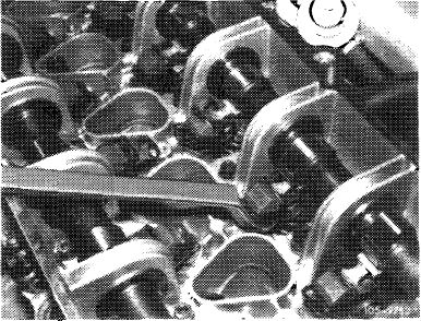
12 Press out all spring clamps with a wrench socket.
|
 |
||
|
|
|||
|
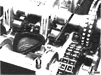
13 Remove all rocker arms with the remover and installer (05-230).
|
’419
|
||
|
|
|||
|
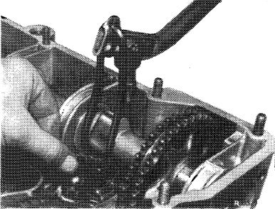
14 Turn crankshaft with combination tool.
|
|||
|
|
|||
|
Attention!
Don’t turn engine on camshafts. Don’t turn engine in
reverse direction of rotation.
|
 |
||
|
|
|||
|
HOO-6498/1
|
|||
|
|
|||
|
01.2-415/6 F3
|
|||
|
|
|||
|
|
|||
|
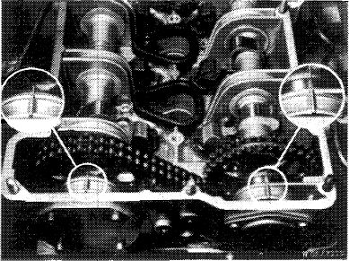
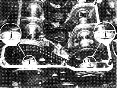
15 Position 1st cylinder of engine at ignition TDC. Marks on camshaft sprockets and camshaft housing must align.
|
 |
||
|
|
|||
 |
|||
|
|
|||
|
16 Remove both expansion bolts of camshaft sprockets. Counterhold camshaft with holder.
|
 |
||
|
|
|||
|
17 Remove upper slide rail in camshaft housing (05-340).
Knock out bearing pins with the impact extractor for this purpose.
|
 |
||
|
|
|||
|
01.2-415/7 F3
|
|||
|
|
|||
|
|
|||
|
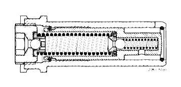
18 Remove chain tensioner (05—310).
19 Push both camshafts to the rear and remove camshaft sprockets.
|
 |
||
|
|
|||
|
20 Remove guide wheel. Knock out bearing pins with impact extractor (M 10 bolts) for this purpose.
|
 |
||
|
|
|||
|
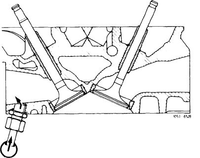
21 Remove guide rail in cylinder head. Knock out bearing pins with impact extractor (6 x 150 mm bolt) for this purpose.
|
 |
||
|
|
|||
|
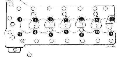
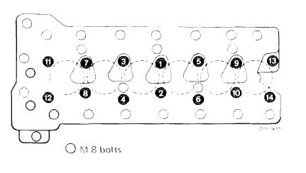
22 Loosen and remove cylinder head bolts in reverse sequence of tightening diagram. Pull out the two M 8 bolts in the timing case with a magnet.
|
 |
||
|
|
|||
|
01.2-415/8 F3
|
|||
|
|
|||
|
|
|||
|
23 Pull up timing chain and press tensioning rail to center of engine. Lift off cylinder head straight up with a cable attached to the suspension eyes.
|
|||
|
|
|||
|
Installation
|
|||
|
|
|||
|
24 Clean cylinder head and crankcase mating surfaces thoroughly.
25 Install new cylinder head gasket.
Note: Two dowel sleeves are press-fit in the crankcase to locate the cylinder head.
|
|||
|
|
|||
|
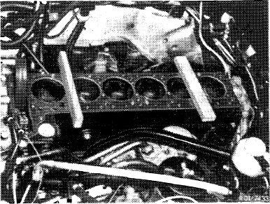
26 Place two locally manufactured wooden boards
(15 x 35 x 240 mm) on the cylinder head gasket, front upright and rear flat.
27 Place cylinder head on board, guide in timing chain and tensioning rail.
28 Lift front of cylinder head and pull out front wooden board toward exhaust side. Lower cylinder head until it fits on the dowel sleeve.
29 Lift rear of cylinder head slightly and pull out wooden board toward exhaust side. Lower cylinder head until it fits over rear dowel sleeve.
Note: If possible, connect cylinder head with camshaft housing to eyes for engine removal, carefully lower with a crane and set down.
|
 |
||
|
|
|||
|
01.2-415/9 F3
|
|||
|
|
|||
|
|
|||
|
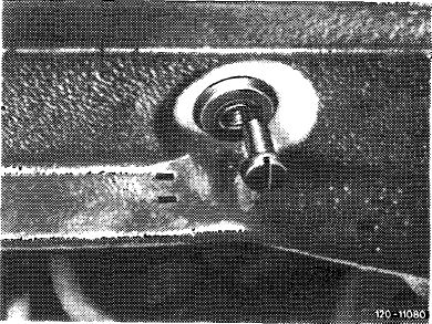
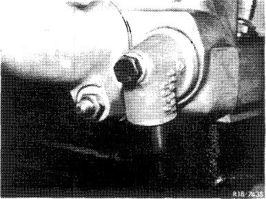
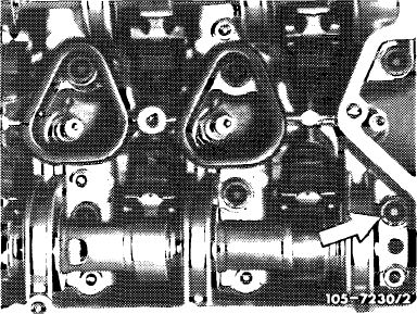
30 Lubricate threads and head surface of cylinder head bolts before installation.
Attention!
Since July of 1974 the clearance on the camshaft housing for the 22 mm dia. washer of cylinder head bolt number 14 has been extended. The former 20 mm dia. washer must be installed on older camshaft housings (arrow).
|
 |
||
|
|
|||
|
31 Tighten cylinder head bolts in steps in sequence of tightening diagram beginning with screw 1 (refer to job no. 01—415 removal and installation of cylinder head).
Tighten screws M 8 to 25 Nm (2.5 kpm).
|
 |
||
|
|
|||
|
Attention!
After all bolts have been tightened, it must be possible to turn both camshafts by hand.
|
|||
|
|
|||
|
32 Install slide rail (2a). For this purpose, pull up timing chain while introducing slide rail with pliers and knocking-in bearing bolts with impact puller. Align slide rail laterally (equalize).
33 Pull up timing chain, position guide wheel (4) with left hand and knock-in lubricated bearing bolt by means of impact puller.
Screw-in screw connection with sealing ring.
|
 |
||
|
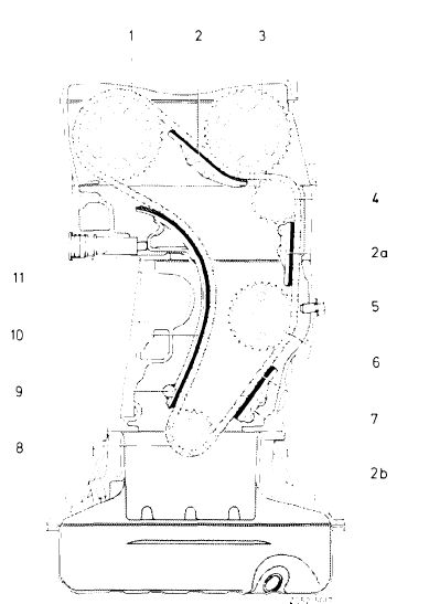
Cham drive
1 Exhaust camshaft sprocket 2— 2b Sliding rail
3 Intake camshaft sprocket
4 Guide wheel
5 Lock bolt
6 Intermediate wheel
7 Timing chain
8 Crankshaft sprocket
9 Tensioning rail bearing pin
10 Tensioning rail
11 Hydraulic chain tensioner
|
|||
|
|
|||
|
01.2-415/10 F3
|
|||
|
|
|||
|
|
||||||||||||||||||||||||||||||||||||||||||||||
|
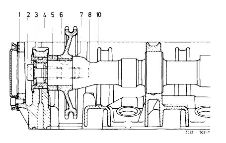
34 Install camshaft sprocket (6) of intake camshaft with spacer (5). Lubricate spacer (3) with engine oil and slide it into bearing (4).
Intake
1 Expansion bolt
2 Washer
3 Spacer
4 Bearing
5 Spacer
6 Camshaft sprocket
7 Woodruff key
8 Camshaft
10 Camshaft housing
|
 |
|||||||||||||||||||||||||||||||||||||||||||||
|
|
||||||||||||||||||||||||||||||||||||||||||||||
|
35 Install camshaft sprocket (6) of exhaust camshaft with timing chain. Lubricate spacer (3) with engine oil and slide it into bearing (4).
|
 |
|||||||||||||||||||||||||||||||||||||||||||||
|
||||||||||||||||||||||||||||||||||||||||||||||
|
|
||||||||||||||||||||||||||||||||||||||||||||||
|
36 During repair jobs, mount necked-down screw (3) with washer (2) only, but do not yet tighten.
|
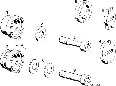 |
|||||||||||||||||||||||||||||||||||||||||||||
|
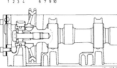
1 Spacer 2nd version without lubricating groove (for pressure oil pump and vacuum pump 2nd version)
2 Washer
3 Expansion bolt
4 Dog (for pressure oil pump and vacuum pump 2nd version)
5 Dog (for vacuum pump 1st version)
6 Dog 1st version with lubricating groove
A = 4.7 mm for vacuum pump 1 st version
A = 8.3 mm for pressure oil pump and vacuum pump
2nd version
8 Spring washers (not valid)
9 Mounting bolt (not valid)
|
||||||||||||||||||||||||||||||||||||||||||||||
|
|
||||||||||||||||||||||||||||||||||||||||||||||
|
37 When 1st cylinder is at ignition TDC the adjustment marks on both camshaft sprockets and camshaft housing must align.
|
 |
|||||||||||||||||||||||||||||||||||||||||||||
|
|
||||||||||||||||||||||||||||||||||||||||||||||
|
01.2-415/11 F3
|
||||||||||||||||||||||||||||||||||||||||||||||
|
|
||||||||||||||||||||||||||||||||||||||||||||||
|
|
|||
|
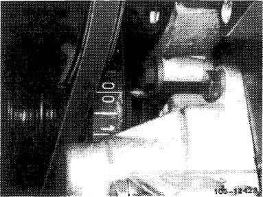
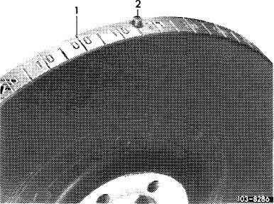
Attention!
If the vibration damper of an engine has a „00” mark for BDC in addition to TDC, the TDC mark is next to pin (2) in the vibration damper.
|
 |
||
|
1 TDC mark
|
|||
|
|
|||
|
38 Install sliding rail in camshaft housing so that the timing chain cannot jump.
|
 |
||
|
|
|||
|
39 Install rigid chain tensioner and tighten by hand.
40 Turn crankshaft with combination tool and adjust to ignition TDC. Check adjustment marks (fig. of point 37).
Check timing, if cylinder head or camshaft housing surfaces have been faced (05—215).
41 Tighten necked-down screw for camshaft sprocket to 80 Nm (8 kpm), while applying counterhold to camshaft by means of holding wrench.
|
 |
||
|
|
|||
|
42 Install rocker arms and spring clamps (05—230).
|
’419
|
||
|
|
|||
|
01.2-415/12 F3
|
|||
|
|
|||
|
|
|||
|
43 Position chain tensioner for insallation and install (05-310).
|
 |
||
|
|
|||
|
44 Adjust valve clearance (05—210).
Further installation instructions in reverse sequence of removal.
|
 |
||
|
|
|||
|
01.2-415/13 F3
|
|||
|
|
|||