Checking, drilling and honing cylinder bores
|
|
|||||||||||||||||||||||||||||||||||||||||||||||||||||
|
01—110 Checking, drilling and honing cylinder bores
|
|||||||||||||||||||||||||||||||||||||||||||||||||||||
|
|
|||||||||||||||||||||||||||||||||||||||||||||||||||||
|
|||||||||||||||||||||||||||||||||||||||||||||||||||||
|
|
|||||||||||||||||||||||||||||||||||||||||||||||||||||
|
Decisive for association is the smallest measured cylinder dia. and the largest measured piston dia.
|
|||||||||||||||||||||||||||||||||||||||||||||||||||||
|
|
|||||||||||||||||||||||||||||||||||||||||||||||||||||
|
Max. wear limit in driving or transverse direction of cylinder bores at upper reversing point of 1st piston ring
|
0,10
|
||||||||||||||||||||||||||||||||||||||||||||||||||||
|
|
|||||||||||||||||||||||||||||||||||||||||||||||||||||
|
When new
|
0,025-0,035
|
||||||||||||||||||||||||||||||||||||||||||||||||||||
|
|
|||||||||||||||||||||||||||||||||||||||||||||||||||||
|
Piston clearance
|
|||||||||||||||||||||||||||||||||||||||||||||||||||||
|
|
|||||||||||||||||||||||||||||||||||||||||||||||||||||
|
Wear limit
|
0,08
|
||||||||||||||||||||||||||||||||||||||||||||||||||||
|
|
|||||||||||||||||||||||||||||||||||||||||||||||||||||
|
Machining tolerances
|
|||||||||||||||||||||||||||||||||||||||||||||||||||||
|
|
|||||||||||||||||||||||||||||||||||||||||||||||||||||
|
Permissible deviation (radial distance) from cylinder shape
|
When new
|
0,007
|
|||||||||||||||||||||||||||||||||||||||||||||||||||
|
|
|||||||||||||||||||||||||||||||||||||||||||||||||||||
|
Wear limit
|
0,025
|
||||||||||||||||||||||||||||||||||||||||||||||||||||
|
|
|||||||||||||||||||||||||||||||||||||||||||||||||||||
|
|||||||||||||||||||||||||||||||||||||||||||||||||||||
|
|
|||||||||||||||||||||||||||||||||||||||||||||||||||||
|
Note
|
|||||||||||||||||||||||||||||||||||||||||||||||||||||
|
|
|||||||||||||||||||||||||||||||||||||||||||||||||||||
|
In particular for a complaint concerning „excessive oil consumption” a measurement of the cylinder bores is essential in addition to a visual inspection.
|
|||||||||||||||||||||||||||||||||||||||||||||||||||||
|
|
|||||||||||||||||||||||||||||||||||||||||||||||||||||
|
01.2-110/1 F3
|
|||||||||||||||||||||||||||||||||||||||||||||||||||||
|
|
|||||||||||||||||||||||||||||||||||||||||||||||||||||
|
|
|||
|
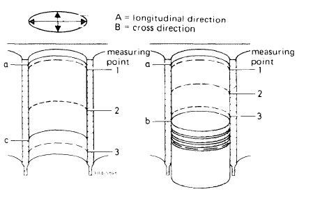
1 Measure the cleaned cylinder bores with an internal tester at measuring points 1, 2 and 3 in longitudinal direction A (piston pin axis) and in cross direction B.
|
|||
|
|
|||
|
When the pistons are installed measuring point 3 will be just barely above the piston, which must be at BDC.
|
 |
||
|
a top reversing point of first piston ring
b BDC of piston
c bottom reversing point of oil scraper ring
|
|||
|
The group number punched into crankcase (arrow), matches the group number of the pistons installed as standard equipment.
On used engines, the original cylinder dia. shows up after thorough cleaning of top land zone.
The difference in diameter of dimension shown on top land zone and the dimension at measuring point 1 generally indicates the respective max. wear.
|
|||
|
|
|||
|
In the event of repairs, hone cylinder bores according to dimensions of available pistons plus piston clearance.
The processing machines used for boring (pre-honing), finish-honing and polishing should be set in accordance with respective operating instructions.
|
|||
|
|
|||
|
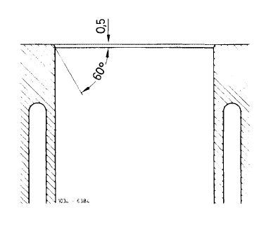
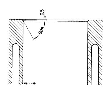
Upon boring, the cylinder bores should be chamfered at upper cylinder end according to drawing.
The lower cylinder end should remain sharp edged without burr.
|
 |
||
|
01.2-110/2 F3
|
|||
|
|
|||
|
|
||||||||||||||||||||||||||||||||||||||||||||||||||||
|
01—120 Grinding crankcase mating surface
|
||||||||||||||||||||||||||||||||||||||||||||||||||||
|
|
||||||||||||||||||||||||||||||||||||||||||||||||||||
|
Data
|
||||||||||||||||||||||||||||||||||||||||||||||||||||
|
|
||||||||||||||||||||||||||||||||||||||||||||||||||||
|
||||||||||||||||||||||||||||||||||||||||||||||||||||
|
|
||||||||||||||||||||||||||||||||||||||||||||||||||||
|
Distance between piston crown and crankcase mating surface
|
Standard size piston Below
|
min. 0.20 max.0.70
|
above 0.25 below 0.15
|
|||||||||||||||||||||||||||||||||||||||||||||||||
|
Oversizes + 0.5 and 1.0
|
Below
|
min. 1.0 max. 1.5
|
below
|
min. 0.55 max.0.95
|
||||||||||||||||||||||||||||||||||||||||||||||||
|
|
||||||||||||||||||||||||||||||||||||||||||||||||||||
|
||||||||||||||||||||||||||||||||||||||||||||||||||||
|
|
||||||||||||||||||||||||||||||||||||||||||||||||||||
|
Note
|
 |
|||||||||||||||||||||||||||||||||||||||||||||||||||
|
Chamfer cylinder bores after grinding.
Adjust valve timing (05—215), if crankcase mating surface has been machined.
|
||||||||||||||||||||||||||||||||||||||||||||||||||||
|
|
||||||||||||||||||||||||||||||||||||||||||||||||||||
|
01.2-120/1 F3
|
||||||||||||||||||||||||||||||||||||||||||||||||||||
|
|
||||||||||||||||||||||||||||||||||||||||||||||||||||