Engine vent, Description of function
|
|
||||
|
01—040 Engine vent — Description of function
|
||||
|
|
||||
|
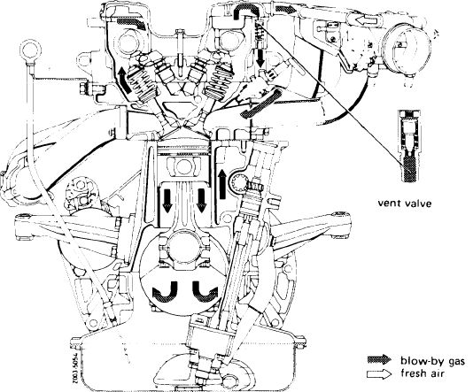
A. Engine with vent valve
|
 |
|||
|
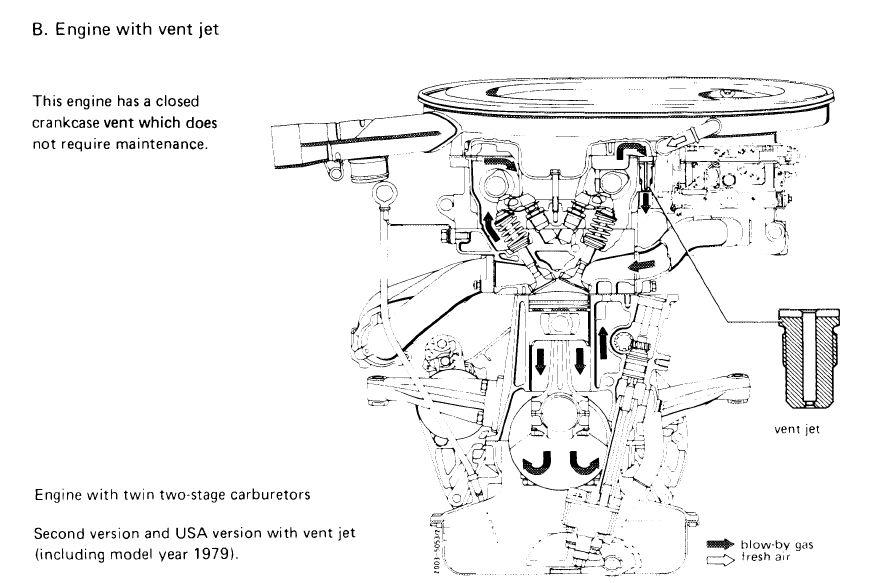
This engine has a closed crankcase vent system which does not require maintenance.
|
||||
|
Engine with electronic fuel injection system.
|
||||
|
|
||||
|
Engine with twin two-stage carburetors
|
 |
|||
|
First version with vent valve
|
||||
|
|
||||
|
01.2-040/1 F3
|
||||
|
|
||||
|
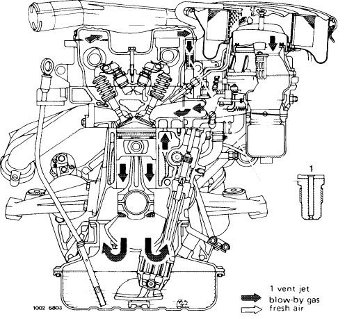
The blow-by gases flow via an oil separator in the cylinder head cover to the vent valve.
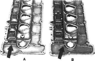
Attention!
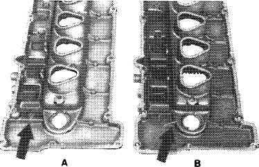
Only use cylinder head covers of version A with oil protection ribs.
|
 |
||
|
|
|||
|
101 – 934)
|
|||
|
|
|||
|
At idle speed and lower speed ranges the blow-by gas will enter the combustion chamber via the vent valve and intake manifold or idle air passage.
The vent valve spring works against the intake manifold vacuum pressure.
Depending on intake manifold vacuum pressure the valve cone will be pulled or pressed up by the valve spring and thus changes the through-flow cross section opening.
Since the through-flow capacity of the vent valve is larger than the amount of blow-by gas from the crankcase, fresh air is also drawn off from the air cleaner of a carburetor engine or from the throttle housing in front of the throttle valve via a pipe of an engine with fuel injection.
The additional fresh air is taken from an air cleaner of a carburetor engine via a hose.
When coasting the high intake manifold pressure will close the vent valve. The very slight amounts of blow-by gas in this case will now travel in reverse direction to the throttle housing via a pipe or the air cleaner via a hose and are drawn off at these points.
Note: Carburetor engines with a vent valve can also be equipped with a vent jet.
|
|||
|
|
|||
|
01.2-040/2 F3
|
|||
|
|
|||
 |
|||
|
|
|||
|
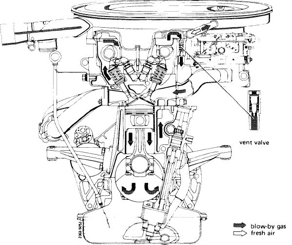
Engine with continuous fuel injection
|
 |
||
|
|
|||
|
01.2-040/3 F3
|
|||
|
|
|||
|
|
|||
|
The blow-by gases flow to the vent jet via an oil separator in the cylinder head cover.
Attention!
Only use cylinder head covers of version A with oil protection ribs.
|
 |
||
|
|
|||
|
101 – 934)
|
|||
|
|
|||
|
At idle speed and in low speed ranges the blow-by gas will enter into the combustion chambers via the vent jet and intake manifold or idle air passage.
|
|||
|
|
|||
|
In lower and medium speed ranges the intake manifold vacuum will cause fresh air to be drawn in from the air cleaner via a hose in addition to the blow-by gas.
|
|||
|
|
|||
|
In the upper speed range blow-by gas will also flow from the fresh air side of the air cleaner depending on the blow-by quantity.
This is drawn off to the combustion chambers via the carburetor or air flow sensor and intake manifold.
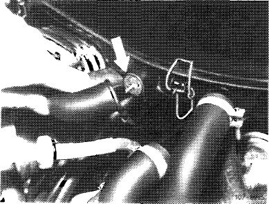
Models for USA, Australia and Japan up to model year of 1977 have a flame guard (arrow) in the engine vent connection.
|
 |
||
|
|
|||
|
01.2-040/4 F3
|
|||
|
|
|||
|
|
|||
|
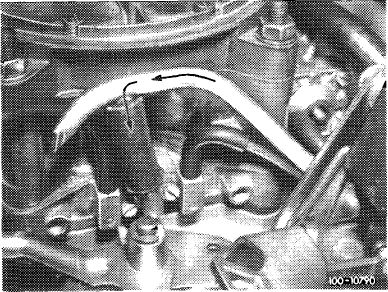
For 1975 and 1976 USA models, 1976 Sweden model and 1976 Japan models the blow-by gas is drawn off to the carburetor via an angle connector (arrow).
|
 |
||
|
|
|||
 |
|||
|
|
|||
|
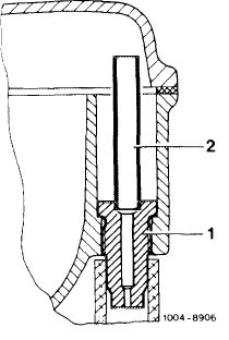
On USA vehicles starting model year 1980 the vent nozzle is mounted with an overflow pipe (2), so that no engine oil is carried along in idle speed air duct.
|
 |
||
|
|
|||
|
01.2-040/5 F3
|
|||
|
|
|||