Removal and installation of front engine mounts
|
|
||||||||||||||||||||||||||||||||||||||||
|
22—211 Removal and installation of front engine mounts
|
||||||||||||||||||||||||||||||||||||||||
|
|
||||||||||||||||||||||||||||||||||||||||
|
||||||||||||||||||||||||||||||||||||||||
|
|
||||||||||||||||||||||||||||||||||||||||
|
Torque wrench with plug-type ratchet, 1/2″ square, 25-130 Nm
Torque wrench with plug-type ratchet, 1/2″ square, 40-220 Nm
|
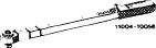 |
001 589 66 21 00
|
||||||||||||||||||||||||||||||||||||||
|
001 589 67 21 00
|
||||||||||||||||||||||||||||||||||||||||
|
|
||||||||||||||||||||||||||||||||||||||||
|
Note
|
 |
|||||||||||||||||||||||||||||||||||||||
|
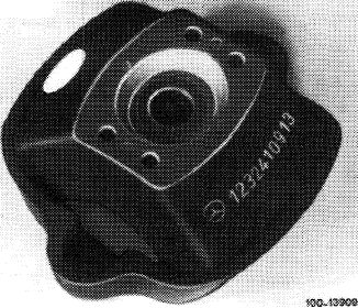
Engine mounts differ with regard to shore hardness.
For identification, a color dot is applied on engine mount in addition to part number.
|
||||||||||||||||||||||||||||||||||||||||
|
|
||||||||||||||||||||||||||||||||||||||||
|
||||||||||||||||||||||||||||||||||||||||
|
|
||||||||||||||||||||||||||||||||||||||||
|
22.8-211/1 F2
|
||||||||||||||||||||||||||||||||||||||||
|
|
||||||||||||||||||||||||||||||||||||||||
|
|
||||
|
Removal
|
 |
|||
|
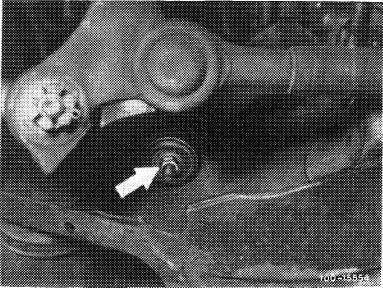
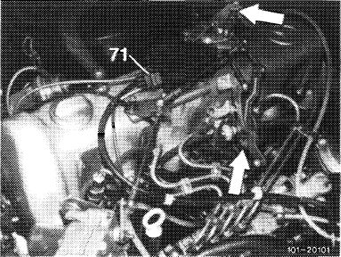
1 Unscrew screws (20) for engine carrier on engine mount from below (arrow).
|
||||
|
|
||||
 |
||||
|
|
||||
|
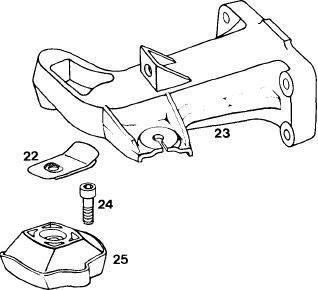
Engine carrier right in model 116.120
20 Screw M 12 x 40
22 Shielding plate
23 Engine carrier
24 Combination screw M 8 x 18
25 Engine mount
|
20
|
|||
|
|
||||
|
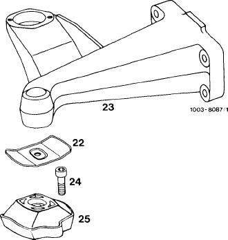
Engine carrier right in model 123
20 Screw M 12 x 40
22 Shielding plate
23 Engine carrier
24 Combination screw M 8 x 18
25 Engine mount
|
 |
1OO4-7952M
|
||
|
20
|
||||
|
|
||||
|
22.8-211/2 F2
|
||||
|
|
||||
|
|
|||
|
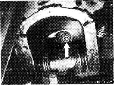
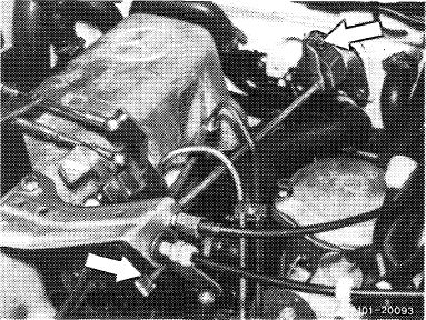
2 Unscrew nuts on engine shock absorbers below (arrow) and remove rubber buffer together with disk washers.
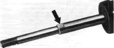
For loosening nuts, apply counterhold to piston rod at spot provided for this purpose (Fig. item 10).
|
 |
||
|
|
|||
|
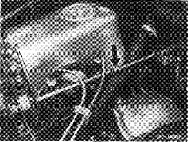
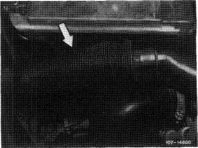
3 Remove longitudinal regulating shaft. For this purpose, disconnect regulating linkage and pull out locking eye (arrow).
|
 |
||
|
Model 116.120
|
|||
|
|
|||
|
On models 116.120 and 123, pull longitudinal regulating shaft out of rubber mount in forward direction and remove in rearward direction.
|
 |
||
|
Model 123
|
|||
|
|
|||
|
On model 126.120, pull longitudinal regulating shaft out of guide lever in rearward direction and remove in forward direction.
|
 |
||
|
Model 126.120
|
|||
|
|
|||
|
22.8-211/3 F2
|
|||
|
|
|||
|
|
|||
|
4 Remove intermediate piece on air cleaner.
|
 |
||
|
|
|||
|
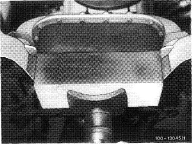
5 Lift engine at oil pan by means of pit lift.
Note: To prevent damage to oil pan, use a wooden base.
The engine can also be lifted be means of a crane and engine hoist attached to front suspension eye.
When lifting, make sure that the fan is not abutting against radiator shell.
6 Remove shielding plate (22).
7 Unscrew screws (24) and remove engine mount.
|
 |
||
|
|
|||
|
Installation
|
|||
|
|
|||
|
8 Position new engine mount and screw down.
9 Insert shielding plates.
Note: Pay attention to installation position.
|
|||
|
|
|||
|
10 Lower engine, while fitting piston rods of engine shock absorbers on frame cross member.
11 Position screws (20) and tighten to 70 Nm.
12 Position rubber buffers and disk washers on engine shock absorbers.
Screw down engine shock absorbers. For this purpose, apply counterhold to piston rod at spot provided for this purpose (arrow).
|
 |
||
|
|
|||
|
22.8-211/4 F2
|
|||
|
|
|||