Removal and installation of rear engine mount
|
|
|||||||||||||||||||||||||||||||||||||||||
|
22—212 Removal and installation of rear engine mount
|
|||||||||||||||||||||||||||||||||||||||||
|
|
|||||||||||||||||||||||||||||||||||||||||
|
|||||||||||||||||||||||||||||||||||||||||
|
|
|||||||||||||||||||||||||||||||||||||||||
|
Note
|
|||||||||||||||||||||||||||||||||||||||||
|
|
|||||||||||||||||||||||||||||||||||||||||
|
Models 116.120, 123.133/153, 123.193®© version and 126.120 are provided with an engine mount without stop since start of series.
Model 123.193 standard version has been provided with an engine mount with stop up to July 1981.
Starting July 1981 likewise without stop.
For this purpose, vehicles with automatic transmission W 4 B 025 (722.120) had to be provided with a rubber buffer on transmission tunnel to prevent transmission vent from knocking against tunnel.
|
 |
 |
|||||||||||||||||||||||||||||||||||||||
|
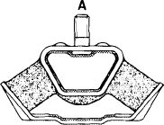
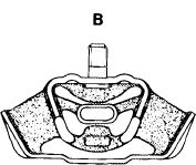
A Engine mount without stop B Engine mount with stop
|
|||||||||||||||||||||||||||||||||||||||||
|
1223 10057
|
|||||||||||||||||||||||||||||||||||||||||
|
|
|||||||||||||||||||||||||||||||||||||||||
|
If a new engine mount with stop is installed, the stop requires adjustment after 1000—1500 km and 7500 km (22-220).
|
|||||||||||||||||||||||||||||||||||||||||
|
|
|||||||||||||||||||||||||||||||||||||||||
|
|||||||||||||||||||||||||||||||||||||||||
|
|
|||||||||||||||||||||||||||||||||||||||||
|
123.133
123.153 123 240 25 18
123.1932)
|
without stop
|
||||||||||||||||||||||||||||||||||||||||
|
|
|||||||||||||||||||||||||||||||||||||||||
|
126.120
|
116 240 04 18
|
without stop
|
|||||||||||||||||||||||||||||||||||||||
|
|
|||||||||||||||||||||||||||||||||||||||||
|
l) Standard version up to July 1981. ) Standard version starting July 1981, (\T) (ui£)version from start of series.
|
|||||||||||||||||||||||||||||||||||||||||
|
|
|||||||||||||||||||||||||||||||||||||||||
|
22.8-212/1 F2
|
|||||||||||||||||||||||||||||||||||||||||
|
|
|||||||||||||||||||||||||||||||||||||||||
|
|
||||||||||||||||||||||||||||||||||||||||||||||||||||||||||||||||||
|
Removal
|
 |
|||||||||||||||||||||||||||||||||||||||||||||||||||||||||||||||||
|
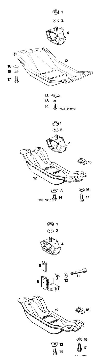
1 Unscrew nuts (1).
2 Unscrew screws (14).
3 Push transmission in upward direction by means of a pit lift at intermediate flange and remove engine mount (4).
|
||||||||||||||||||||||||||||||||||||||||||||||||||||||||||||||||||
|
||||||||||||||||||||||||||||||||||||||||||||||||||||||||||||||||||
|
4 On model 123.193 standard version up to July 1981, unscrew adjusting screw (11) and take engine mount (4) out of holder.
|
||||||||||||||||||||||||||||||||||||||||||||||||||||||||||||||||||
|
Models 123.133/153 and 123.193 standard version starting July 1981 ,(~J^)(us£)version from start of series
|
||||||||||||||||||||||||||||||||||||||||||||||||||||||||||||||||||
|
||||||||||||||||||||||||||||||||||||||||||||||||||||||||||||||||||
|
Model 123.193 standard version up to July 1981
|
||||||||||||||||||||||||||||||||||||||||||||||||||||||||||||||||||
|
||||||||||||||||||||||||||||||||||||||||||||||||||||||||||||||||||
|
11 Adjusting screw M 8 x 75
|
||||||||||||||||||||||||||||||||||||||||||||||||||||||||||||||||||
|
22.8-212/2 F2
|
||||||||||||||||||||||||||||||||||||||||||||||||||||||||||||||||||
|
|
||||||||||||||||||||||||||||||||||||||||||||||||||||||||||||||||||
|
|
||||
|
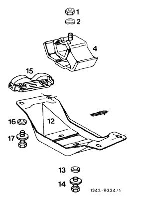
Model 126.120
1 Nut M 12 x 1.5
2 Spring washer 4 Engine mount
12 Engine carrier 16 Washer 10.5
|
17 Combination screw M 10 x 22
13 Washer
14 Combination screw M 8 x 15
15 Nut holder
|
 |
||
|
|
||||
|
Installation
|
||||
|
|
||||
|
5 On model 123.193 standard version up to July 1981, place new engine mount into holder (8).
6 Place new engine mount with or without holder (depending on model) on engine carrier (12).
7 On model 123.193 screw-in adjusting screw (11) (do not tighten).
8 Lower transmission.
9 Position screws (14) and tighten to 30 Nm.
10 Screw-on nut (1). Torque reference value 70 Nm.
11 On model 123.193, adjust engine stop (22-220).
|
||||
|
|
||||
|
22.8-212/3 F2
|
||||
|
|
||||