Repiacement of pipe connection, delivery valve or copper sealing ring on injection pump
|
|
||||||||||||||||||||||||||||||||||||||||||||||||
|
07.1—210 Repiacement of pipe connection, delivery valve or copper sealing ring on injection pump
Job no. of flat rates or standard texts and flat rates data 07—8627.
|
||||||||||||||||||||||||||||||||||||||||||||||||
|
|
||||||||||||||||||||||||||||||||||||||||||||||||
|
||||||||||||||||||||||||||||||||||||||||||||||||
|
|
||||||||||||||||||||||||||||||||||||||||||||||||
|
Note
|
||||||||||||||||||||||||||||||||||||||||||||||||
|
|
||||||||||||||||||||||||||||||||||||||||||||||||
|
To reduce hydrocarbons in exhaust gases, relief throttles are installed in pipe connections of injection pump.
|
||||||||||||||||||||||||||||||||||||||||||||||||
|
|
||||||||||||||||||||||||||||||||||||||||||||||||
|
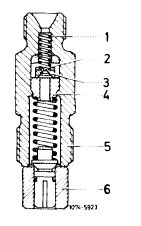
Relief throttle (2) is a poppet valve (3) with an orifice of 0.6 mm dia. opening in direction of injection nozzle. Valve seat (4) is riveted into pipe connection.
|
||||||||||||||||||||||||||||||||||||||||||||||||
|
|
||||||||||||||||||||||||||||||||||||||||||||||||
|
1 Compression spring
2 Relief throttle
3 Peppet valve
4 Valve seat
5 Pipe connection
6 Delivery valve holder with valve
|
 |
|||||||||||||||||||||||||||||||||||||||||||||||
|
|
||||||||||||||||||||||||||||||||||||||||||||||||
|
07.1.8-210/1 F3
|
||||||||||||||||||||||||||||||||||||||||||||||||
|
|
||||||||||||||||||||||||||||||||||||||||||||||||
|
|
|||
|
The relief throttle allows fuel to pass through freely in the direction of the injection nozzle. The pressure wave travelling toward the injection pump from the injection nozzle is caused by the secondary pumping action of the needle valve as it closes; this is attenuated by the relief throttle and prevented from returning to the injection nozzle where it would otherwise cause secondary injection. This in turn would increase the hydrocarbon content of the exhaust gases.
|
|||
|
|
|||
|
Removal
|
 |
||
|
1 Clean injection pump at injection line cap r. jts and at pipe connections.
2 Unscrew injection lines and pipe connection.
Attention:
Do not release assembly (2) because basic injection pump adjustment will otherwise have to be corrected on injection pump test bed.
3 Remove compression spring, copper sealing ring and delivery valve with holder.
4 Flush out injection pump suction chamber, using hand-operated feed pump. Remove foreign matter if necessary.
|
|||
|
|
|||
|
Installation
|
|||
|
|
|||
|
5 Clean delivery valve and holder, checking for damage and freedom of movement.
|
|||
|
|
|||
|
07.1.8-210/2 F3
|
|||
|
|
|||
|
|
|||
|
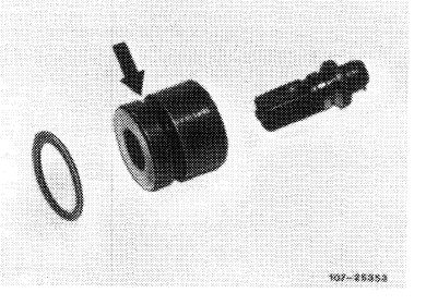
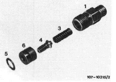
6 Position new copper sealing ring (5) beneath delivery valve holder (6).
On 1st version, the annular groove (arrow) must point in downward direction toward pump element.
|
 |
||
|
1st version
|
|||
|
|
|||
|
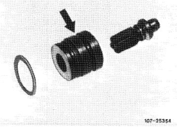
On 2nd version, the annular groove (arrow) must point toward delivery valve.
|
|||
|
|
|||
|
2nd version
|
 |
||
|
|
|||
|
1 Pipe connection
3 Compression spring
4 Delivery valve
5 Copper sealing ring
6 Delivery valve holder
|
 |
||
|
|
|||
|
7 Smear thread of pipe connection (1) with oil, insert and torque to 40—50 Nm in one step.
8 Connect injection lines and vent injection system (07.1-140).
9 Run engine, checking for leakage and smooth idling.
|
|||
|
|
|||
|
07.1.8-210/3 F3
|
|||
|
|
|||