Installation of injection pump (with locking screw)
|
|
||||
|
07.1—201 Installation of injection pump (with locking screw)
|
||||
|
|
||||
|
Adjusting value
|
||||
|
|
||||
|
Set engine to -15° after TDC of 1st cylinder
|
||||
|
|
||||
|
Special tools
|
||||
|
|
||||
|
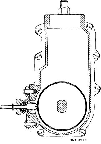
Locking screw
|
11004-11773
|
601 589 05 21 00
|
||
|
|
||||
|
Driving square 1/2″, 80 mm for rotating engine
|
(cooooo<>o\
11004-10282
|
617 589 00 16 00
|
||
|
|
||||
|
Note
|
||||
|
|
||||
|
Remove engine pump (07.1—200).
|
||||
|
|
||||
|
Installation
|
 |
|||
|
1 Rotate engine in direction of rotation once and set to —15° after TDC of 1st cylinder.
Note: Clearances must be compensated.
|
||||
|
|
||||
|
2 Mount new gasket.
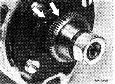
3 Lock injection pump. For this purpose, rotate pump shaft until 4th tooth on driver after tooth gap is in alignment with mark (arrows).
|
 |
|||
|
|
||||
|
07.1.8-201/1 F3
|
||||
|
|
||||
|
|
|||
|
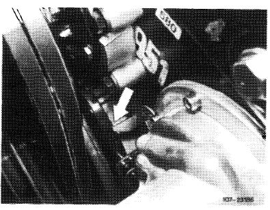
4 Slip in locking screw until there is a noticeable lock, turn camshaft slightly, if required.
Tighten coupling nut manually.
|
 |
||
|
|
|||
|
5 Slip coupling sleeve on driver.
6 Install injection pump, tighten.
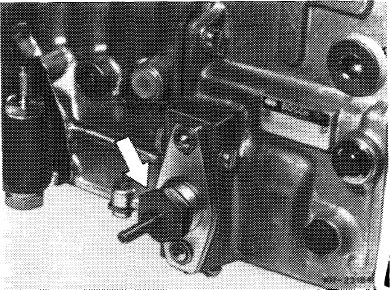
7 Remove locking screw (arrow). Additional jobs (07.1-200 starting item 16).
|
 |
||
|
|
|||
|
07.1.8-201/2 F3
|
|||
|
|
|||