Test program
|
|
|||||
|
14—100 Test program
|
|||||
|
|
|||||
|
Model year 1977/78/79
|
|||||
|
|
|||||
|
A. Federal version, tourist vehicles Federal version
|
|||||
|
|
|||||
|
For complaints such as:
|
Poor warming-up characteristics of engine, poor idle speed, engine not accelerating or splashing during acceleration, check emission control system for function.
|
||||
|
|
|||||
|
Test conditions:
|
Engine at operating temperature, run engine at idle speed.
|
||||
|
|
|||||
|
Test the following:
|
EGR, air injection and fuel evaporation control system.
|
||||
|
|
|||||
|
Function diagram model year 1977
|
|||||
|
|
|||||
 |
|||||
|
|
|||||
|
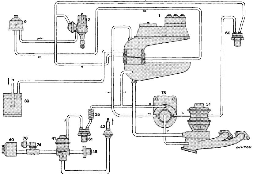
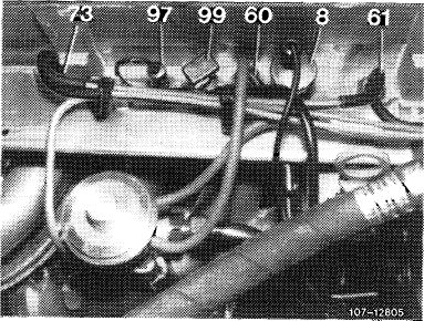
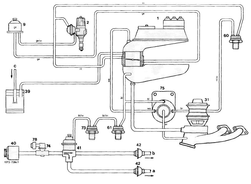
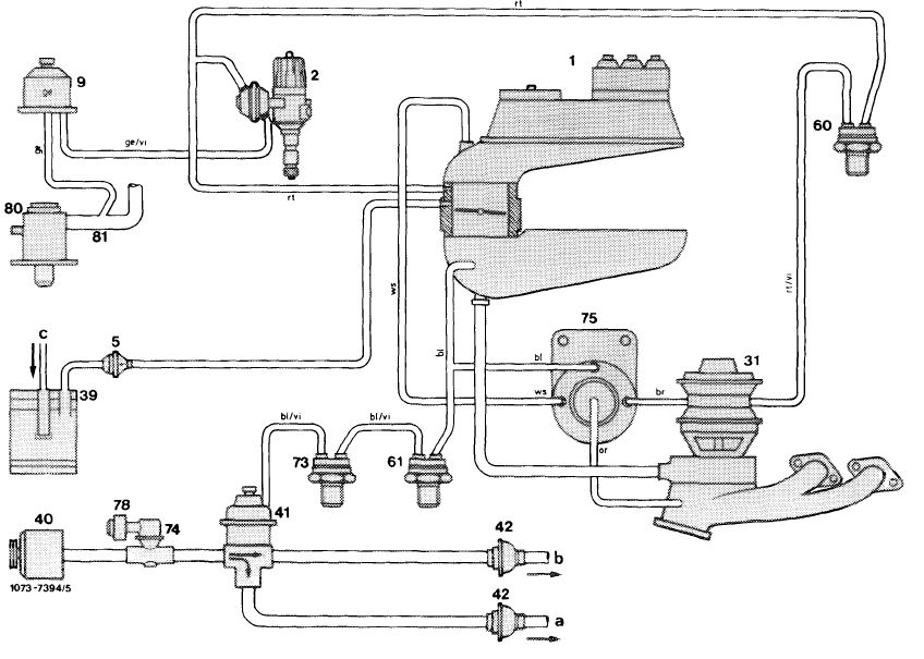
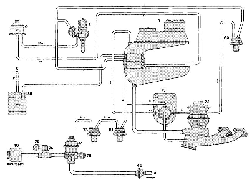
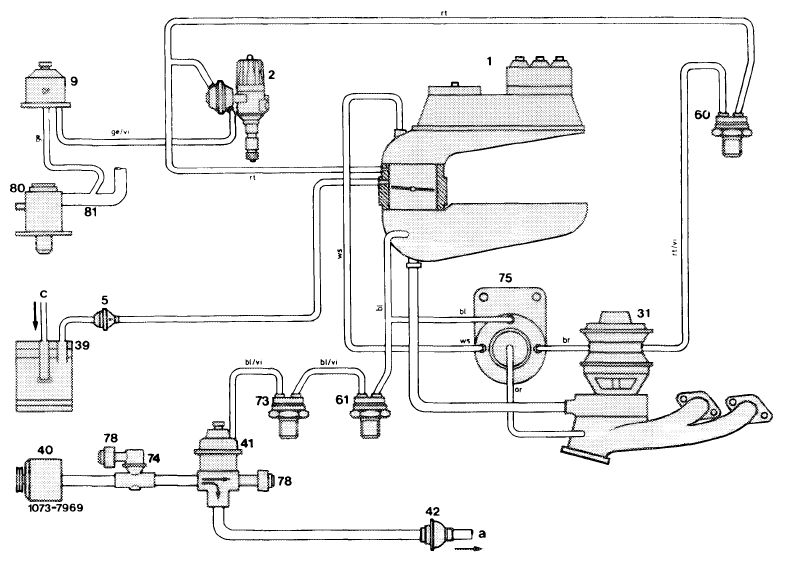
1 Mixture controller
2 Ignition distributor
9 Switch-over valve ignition
31 EGR valve_
35 Check valve
|
39 Charcoal canister
40 Air pump
41 Diverter valve (air switch-over valve)
42 Check valve 45 Air filter
|
60 Thermovalve 40 °C
61 Thermovalve 17 °C
74 Pressure relief valve
75 Pressure transducer 78 Air filter for silencing
|
a Air injection line
b Connection tank vent
|
||
|
|
|||||
|
14.2-100/1 USA 1977/78/79 F2
|
|||||
|
|
|||||
|
|
|||||||||||||||||||||||||||||||||||||||||||||
|
Function diagram model year 1978/79
|
|||||||||||||||||||||||||||||||||||||||||||||
|
|
|||||||||||||||||||||||||||||||||||||||||||||
 |
|||||||||||||||||||||||||||||||||||||||||||||
|
|
|||||||||||||||||||||||||||||||||||||||||||||
|
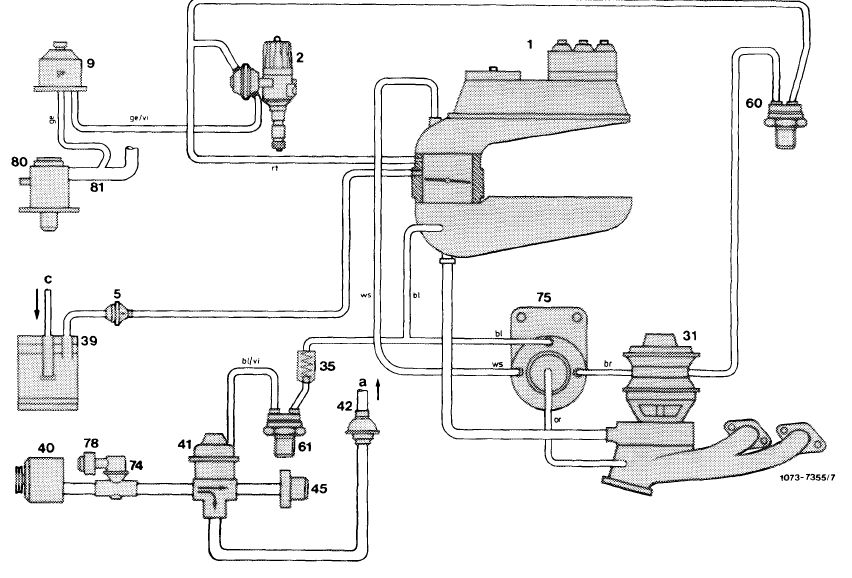
1 Mixture controller
2 Ignition distributor
5 Regenerating valve (purge
valve)
9 Switch-over valve ignition 31 EGR valve
|
35 Check valve
39 Charcoal canister
40 Air pump
41 Diverter valve (air switch-over valve)
42 Check valve
|
45 Air filter
60 Thermovalve 40 °C
61 Thermovalve 17 °C
74 Pressure relief valve
75 Pressure transducer
|
78 Air filter for silencing
80 Auxiliary air valve
81 Contour hose
a Air injection line
b Connection tank vent
|
||||||||||||||||||||||||||||||||||||||||||
|
|
|||||||||||||||||||||||||||||||||||||||||||||
|
 |
||||||||||||||||||||||||||||||||||||||||||||
 |
 |
||||||||||||||||||||||||||||||||||||||||||||
|
|
|||||||||||||||||||||||||||||||||||||||||||||
|
14.2-100/2 USA 1977/78/79 F2
|
|||||||||||||||||||||||||||||||||||||||||||||
|
|
|||||||||||||||||||||||||||||||||||||||||||||
|
|
||||
 |
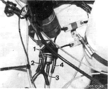
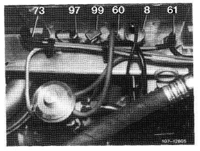
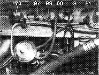
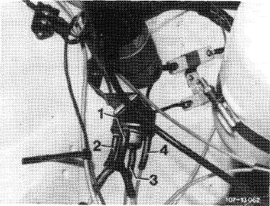
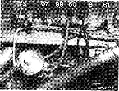
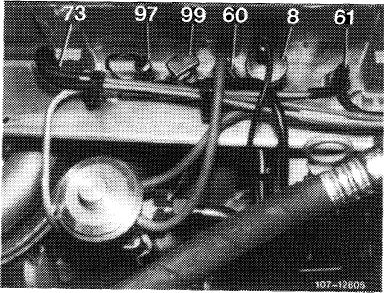
Testing vacuum lines
Test layout of vacuum lines on pressure transducer and intake pipe.
Note that connections on pressure transducer are identified with color rings. The attached vacuum lines should have the same color.
|
 |
||
|
1 Connection intake pipe vacuum (blue)
2 Connection vent line (white)
3 Connection exhaust gas backpressure line (orange)
4 Connection vacuum line to EGR valve (brown)
|
||||
|
On black thermovalve 40 °C (60) the red vacuum line should be plugged to diagonal connection, and the rubber hose to straight connection. Check all pertinent vacuum lines for leaks and blow out vacuum connections.
|
 |
|||
|
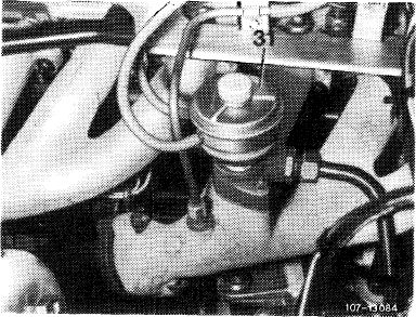
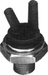
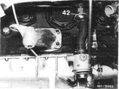
Testing thermovalve 40 °C (60)
The thermovalve is identified by a black plastic section and the designation „50 AA 4” punched into metal section. Pull-off vacuum hose at straight connection, let engine run and accelerate.
Vacuum should be felt at free connection.
During removal and installation of thermovalve make sure that the small connecting pipes are not damaged.
|
||||
|
|
||||
|
14.2-100/3 USA 1977/78/79 F2
|
||||
|
|
||||
|
|
|||
 |
 |
||
|
1O7-123M
|
|||
 |
|||
 |
|||
|
|
|||
|
14.2-100/4 USA 1977/78/79 F2
|
|||
|
|
|||
|
|
||||
 |
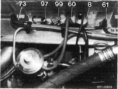
Testing vacuum lines
The blue vacuum line from intake pipe should be connected to blue line and diagonal connection of thermovalve (61) by means of a distributor and check valve. The check valve should be plugged on with connection (A) in direction of intake pipe.
The blue/purple vacuum line of straight connection of thermovalve (61) leads to diverter valve (41).
|
 |
||
|
Testing vacuum
Pull vacuum line from diagonal connection of thermovalve (61), connect vacuum gauge or keep closed with finger. Vacuum should be available at idle speed. If not, test vacuum lines for leaks and blow out vacuum draw-off line (tapping line) at intake pipe.
If vacuum is available, test thermovalve (61) and renew, if required.
|
 |
|||
|
Testing thermovalve 17 °C (61)
The thermovalve is identified by a blue plastic section and the designation „50 AB 5” punched into metal section.
Pull-off blue/purple vacuum line, run engine.
Vacuum should be available at free connection.
If thermovalve is in order, renew diverter valve (41).
|
 |
|||
 |
||||
|
107-10895
|
||||
|
|
||||
|
14.2-100/5 USA 1977/78/79 F2
|
||||
|
|
||||
|
|
|||
 |
 |
||
|
|
|||
|
End of test
|
|||
|
|
|||
|
14.2-100/6 USA 1977/78/79 F2
|
|||
|
|
|||
|
|
|||||
|
B. California version
|
|||||
|
|
|||||
|
For complaints such as: Poor warming-up characteristics of engine, poor idle speed, engine not accelerating or
splashing during acceleration, check emission control system for function.
|
|||||
|
|
|||||
|
Test conditions:
|
Engine at operating temperature, run engine at idle speed.
|
||||
|
|
|||||
|
Test the following:
|
EGR, air injection and fuel evaporation control system.
|
||||
|
|
|||||
|
Function diagram model year 1977
|
|||||
|
|
|||||
 |
|||||
|
|
|||||
|
1 Mixture controller
2 Ignition distributor
9 Switch-over valve ignition
31 EGR valve
39 Charcoal canister
|
40 Air pump
41 Air switch-over valve
42 Check valve
60 Thermovalve 40 °C
|
61 Thermovalve 1 7 °C
73 Thermovalve 50 °C
74 Pressure relief valve
75 Pressure transducer
|
78 Air filter for silencing
a Air injection line cylinder head
b Air injection line between catalysts
c Connection tank vent
|
||
|
|
|||||
|
14.2-100/7 USA 1977/78/79 F2
|
|||||
|
|
|||||
|
|
|||||
|
Function diagram model year 1978/79
|
|||||
|
|
|||||
 |
|||||
|
|
|||||
|
1 Mixture controller
2 Ignition distributor 5 Regenerating valve
9 Switch-over valve ignition
31 EGR valve
|
39 Charcoal canister
40 Air pump
41 Air switch-over valve
42 Check valve
60 Thermovalve 40 °C
|
61 Thermovalve 17 °C
73 Thermovalve 50 °C
74 Pressure relief valve
75 Pressure transducer 78 Air filter for silencing
|
80 Auxiliary air valve
81 Contour hose
a Air injection line cylinder head
b Air injection line between catalysts
c Connection tank vent
|
||
|
|
|||||
|
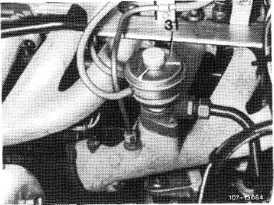
Testing EGR
Pull-off brown vacuum line on EGR valve (31) and slowly increase idle speed.
|
 |
||||
|
Engine runs irregularly starting at approx. 1200/min or comes to a stop.
|
Engine operation continues without stop.
|
||||
|
|
|||||
|
14.2-100/8 USA 1977/78/79 F2
|
|||||
|
|
|||||
|
|
|||
|
Testing vacuum lines
Test layout of vacuum lines on transducer and intake pipe.
Note that connections on pressure transducer are identified with color rings. The plugged-on vacuum lines should have the same color.
|
|||
|
|
|||
|
1 Connection intake pipe vacuum (blue)
2 Connection vent line (white)
3 Connection exhaust gas backpressure line (orange)
4 Connection vacuum line to EGR valve (brown)
|
 |
||
|
|
|||
|
On black thermovalve 40 °C (60) the red vacuum line should be connected to diagonal connection, and the rubber hose to straight connection. Check all pertinent vacuum lines for leaks and blow out vacuum draw-off connections.
|
 |
||
|
Testing thermovalve 40 °C (60)
The thermovalve is identified by black plastic section and by the designation „50 AA 4” punched into metal section. Pull-off vacuum hose at straight connection, keep engine running and accelerate.
Vacuum should be available at free connection.
When removing and installing thermovalve, make sure that the small connecting pipes are not damaged.
|
|||
|
|
|||
|
14.2-100/9 USA 1977/78/79 F2
|
|||
|
|
|||
|
|
|||
 |
 |
||
|
107-12314
|
|||
 |
|||
 |
|||
|
|
|||
|
14.2-100/10 USA 1977/78/79 F 2
|
|||
|
|
|||
|
|
|||
 |
1-57- 13-52^
|
||
 |
|||
 |
|||
|
W7-10895
|
|||
|
|
|||
|
14.2-100/11 USA 1977/78/79 F2
|
|||
|
|
|||
|
|
|||
 |
 |
||
 |
|||
|
End of test
14.2-100/12 USA 1977/78/79 F2
|
|||
|
|
|||
|
|
|||||
|
C. Tourist vehicles California version
|
|||||
|
|
|||||
|
For complaints such as:
|
Poor warming-up characteristics of engine, poor idle speed, engine not accelerating or splashing during acceleration, check emission control system for function.
|
||||
|
|
|||||
|
Test conditions:
|
Engine at operating temperature, run engine at idle speed.
|
||||
|
|
|||||
|
Test the following:
|
EGR, air injection and fuel evaporation control system.
|
||||
|
|
|||||
|
Function diagram model year 1977
|
|||||
|
|
|||||
 |
|||||
|
|
|||||
|
1 Mixture controller
2 Ignition distributor
9 Switch-over valve ignition
31 EGR valve
|
39 Charcoal canister
40 Air pump
41 Air switch-over valve
42 Check valve
|
60 Thermovalve 40 °C
61 Thermovalve 17 °C
73 Thermovalve 50 °C
74 Pressure relief valve
|
75 Pressure transducer 78 Air filter for silencing a Air injection line
cylinder head c Connection tank vent
|
||
|
|
|||||
|
14.2-100/13 USA 1977/78/79 F2
|
|||||
|
|
|||||
|
|
|||||||||||||||||||||||||||||||||||||||||||||||||||||
|
Function diagram model year 1978/79
|
|||||||||||||||||||||||||||||||||||||||||||||||||||||
|
|
|||||||||||||||||||||||||||||||||||||||||||||||||||||
 |
|||||||||||||||||||||||||||||||||||||||||||||||||||||
|
|
|||||||||||||||||||||||||||||||||||||||||||||||||||||
|
Thermovalve 1 7 °C Thermovalve 50 °C Pressure relief valve Pressure transducer Air filter for silencing
|
80 Auxiliary air valve
81 Contour hose
a Air injection line
cylinder head c Connection tank vent
|
|||||||||||||||||||||||||||||||||||||||||||||||||||
|
|
|||||||||||||||||||||||||||||||||||||||||||||||||||||
|
|||||||||||||||||||||||||||||||||||||||||||||||||||||
|
|
|||||||||||||||||||||||||||||||||||||||||||||||||||||
|
14.2-100/14 USA 1977/78/79 F2
|
|||||||||||||||||||||||||||||||||||||||||||||||||||||
|
|
|||||||||||||||||||||||||||||||||||||||||||||||||||||
|
|
||||
 |
Test vacuum lines
Test layout of vacuum lines on transducer and intake pipe.
Note that connections on pressure transducer are identified with color rings. The plugged-on vacuum lines should have the same color.
|
 |
||
|
1 Connection intake pipe vacuum (blue)
2 Connection vent line (white)
3 Connection exhaust gas backpressure line (orange)
4 Connection vacuum control line to EGR valve (brown)
|
||||
|
On black thermovalve 40 °C (60) the red vacuum line should be connected to diagonal connection, and the rubber hose to straight connection. Check all pertinent vacuum lines for leaks and blow out vacuum draw-off connections.
|
 |
|||
|
Test thermovalve 40 °C (60)
The thermovalve is identified by black plastic section and by the designation „50 AA 4” punched into metal section.
Pull-off vacuum hose at straight connection, keep engine running and accelerate.
Vacuum should be available at free connection.
When removing and installing thermovalve, make sure that the small connecting pipes are not damaged.
|
||||
|
|
||||
|
14.2-100/15 USA 1977/78/79 F2
|
||||
|
|
||||
|
|
|||||
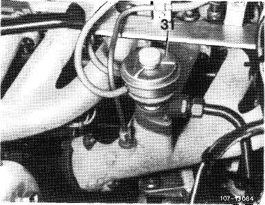
 |
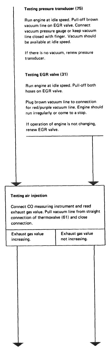
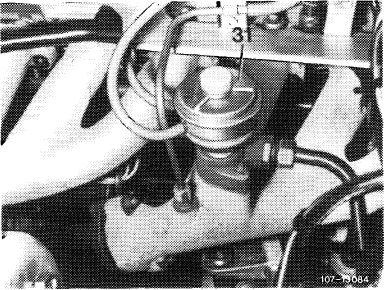
Test pressure transducer (75)
Run engine at idle. Pull-off brown vacuum line on EGR valve. Connect vacuum gauge or keep vacuum line closed with finger. Vacuum should be available at idle speed.
If there is no vacuum, renew pressure transducer.
|
 |
|||
|
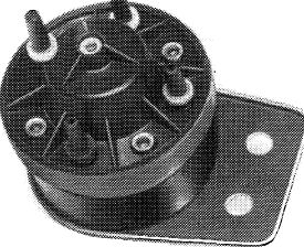
Test EGR valve (31)
Run engine at idle speed. Pull-off both hoses on EGR valve.
Plug brown vacuum line to connection for red/purple vacuum line. Engine should run irregularly or come to a stop.
If operation of engine is not changing, renew EGR valve.
|
|||||
|
107-12314
|
|||||
 |
|||||
 |
|||||
|
|
|||||
|
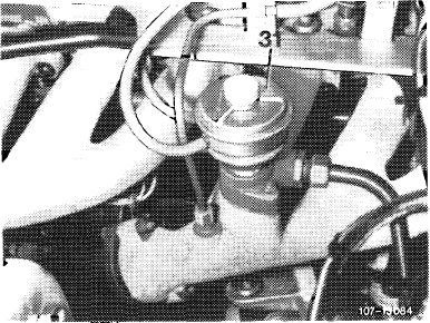
Testing air injection
Connect CO measuring instrument and read exhaust gas emission value. Change vacuum hose from straight plug connection of thermo-valve (73) to straight plug connection of thermovalve (61).
|
|||||
|
|
|||||
|
Exhaust gas value clearly decreasing.
|
Exhaust gas value not decreasing.
|
||||
|
|
|||||
|
14.2-100/16 USA 1977/78/79 F2
|
|||||
|
|
|||||
|
|
|||
|
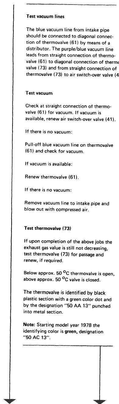
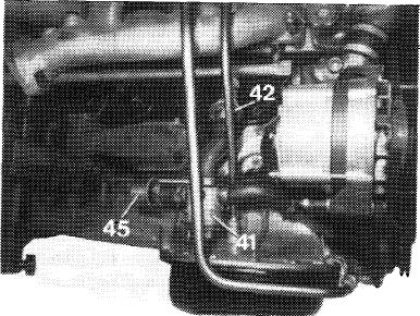
Test vacuum lines
The blue vacuum line from intake pipe should be connected to diagonal connection of thermovalve (61) by means of a distributor. The purple/blue vacuum line leads from straight connection of thermovalve (61) to diagonal connection of thermovalve (73) and from straight connection of thermovalve (73) to air switch-over valve (41).
|
 |
||
|
|
|||
|
Test vacuum
Check at straight connection of thermovalve (61) for vacuum. If vacuum is available, renew air switch-over valve (41).
If there is no vacuum:
Pull-off blue vacuum line on thermovalve (61) and check for vacuum.
If vacuum is available: Renew thermovalve (61). If there is no vacuum:
Remove vacuum line to intake pipe and blow out with compressed air.
|
 |
||
 |
|||
|
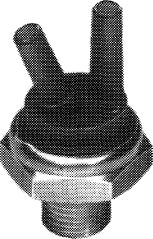
Test thermovalve (73)
If upon completion of the above jobs the exhaust gas value is still not decreasing, test thermovalve (73) for passage and renew, if required.
Below approx. 50 °C thermovalve is open, above approx. 50 °C valve is closed.
The thermovalve is identified by black plastic section with a green color dot and by the designation „50 AA 13” punched into metal section.
Note: Starting model year 1978 the identifying color is green, designation „50 AC 13”.
|
|||
|
|
|||
|
14.2-100/17 USA 1977/78/79 F2
|
|||
|
|
|||
|
|
|||||
|
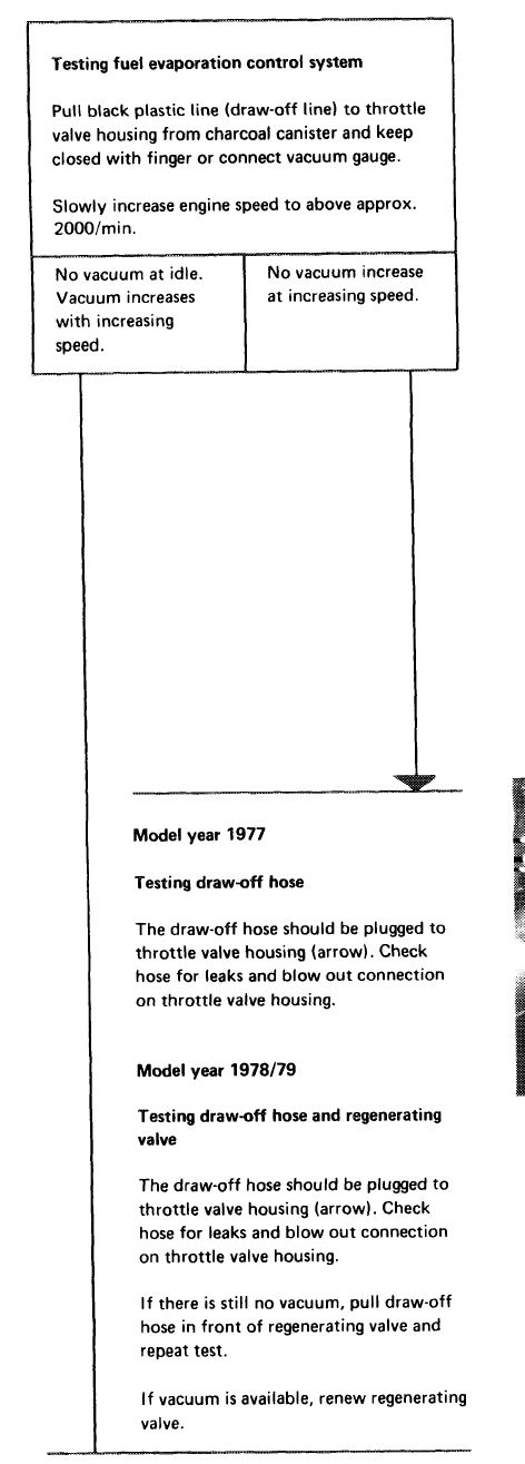
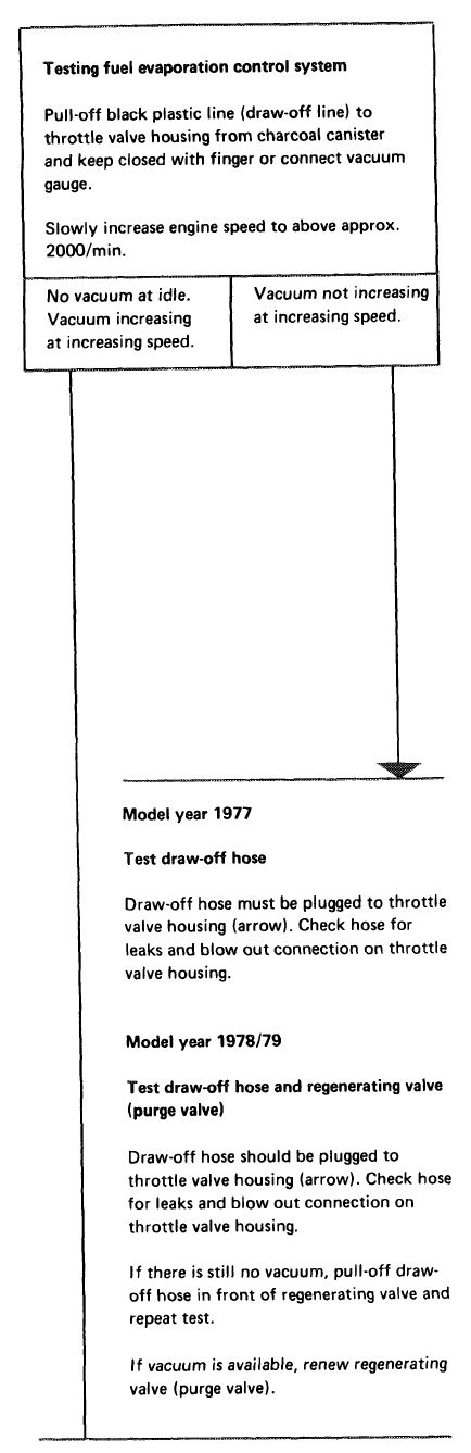
Testing fuel evaporation control system
Pull-off black plastic line (draw-off line) to throttle valve housing from charcoal canister and keep closed with finger or connect vacuum gauge.
Slowly increase engine speed to above approx. 2000/min.
|
|||||
|
|
|||||
|
No vacuum at idle. Vacuum increasing at increasing speed.
|
Vacuum not increasing at increasing speed.
|
||||
|
|
|||||
|
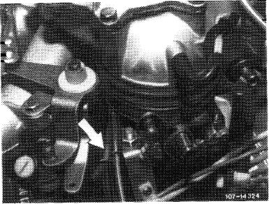
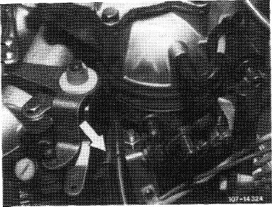
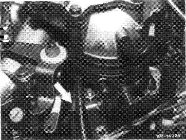
Model year 1977 Test draw-off hose
Draw-off hose must be plugged to throttle valve housing (arrow). Check hose for leaks and blow out connection on throttle valve housing.
|
 |
||||
|
End of test
|
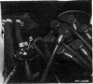
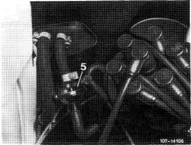
Model year 1978/79
Test draw-off hose and regenerating valve (purge valve)
Draw-off hose should be plugged to throttle valve housing (arrow). Check hose for leaks and blow out connection on throttle valve housing.
If there is still no vacuum, pull-off draw-off hose in front of regenerating valve and repeat test.
If vacuum is available, renew regenerating valve (purge valve).
|
||||
 |
|||||
|
|
|||||
|
14.2-100/18 USA 1977/78/79 F2
|
|||||
|
|
|||||