Oil circuit, oil pressure, pressure relief valve and oil filter
|
|
||||
|
18—005 Oil circuit, oil pressure, pressure relief valve and oil filter
|
||||
|
|
||||
|
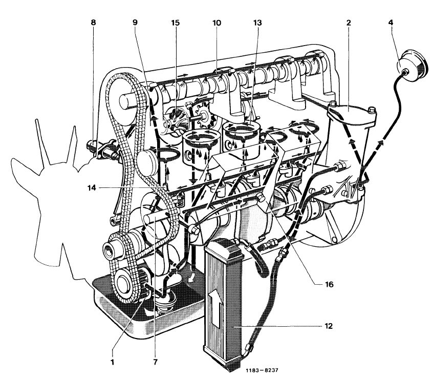
Oil circuit
|
||||
|
|
||||
 |
||||
|
|
||||
|
1 Oil pump with integrated pressure relief valve
2 Oil filter
4 Oil pressure gage (readout)
7 Intermediate sprocket shaft
|
8 Chain tensioner
9 1st camshaft bearing 10 Oil pipe
12 Air-oil cooler
|
13 Piston
14 Oil spray nozzle
15 Exhaust gas turbocharger
16 Injection pump
|
||
|
|
||||
|
Attention!
The oil circuit is controlled by a thermostat in oil filter (for operation, refer to section covering oil filter).
|
||||
|
|
||||
|
18.8-005/1 F 2
|
||||
|
|
||||
|
|
|||
|
Oil pressure
At operating pressure, the oil pressure at idle should not drop to 0.3 bar gage pressure.
During acceleration, the oil pressure should rise again immediately and should attain at least 3 bar gage pressure at 3000/min.
In model 126, the oil pressure is no longer transmitted to oil pressure gage (readout) in instrument cluster by way of a capillary tube as up to now, but the oil pressure gage is electrically activated by an oil pressure transmitter (2), which is screwed into oil filter.
|
 |
||
|
|
|||
|
Pressure relief valves
|
|||
|
|
|||
|
Opening pressure of pressure relief valves
|
bar gage pressure
|
||
|
|
|||
|
Bypass valve in oil filter
|
3.5
|
||
|
|
|||
|
Pressure relief valve in oil pump
|
|||
|
|
|||
|
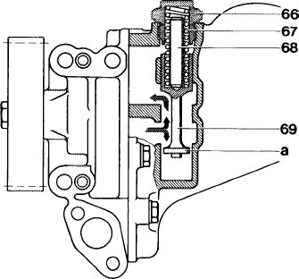
Pressure relief valve in oil pump
|
1183-8064
|
||
|
The damped oil pressure relief valve (7 bar gage pressure) is integrated in oil pump.
|
|||
|
66 Closing plug
67 Compression spring
68 Pin
69 Piston a Washer
|
|||
|
|
|||
|
A damping device (washer „a”) has been installed to make sure that the pulsating oil pressure generated by the oil pump is not transferred to piston (69) of pressure relief valve with subsequent de-activating noise.
Starting at an oil pressure of 7 bar gage pressure the piston (69) is displaced against the pressure of compression spring (67) and clears the de-activation cross section.
|
|||
|
|
|||
|
18.8-005/2 F 2
|
|||
|
|
|||
|
|
|||
|
Simultaneously some of the oil (arrow) flows into the area behind washer (a) by way of two control cross sections in washer (a). The oil flowing through the control cross sections opposes the piston movements initiated by the pulsating oil pressure and will thereby dampen the piston.
|
|||
|
|
|||
|
Oil filter
|
|||
|
|
|||
|
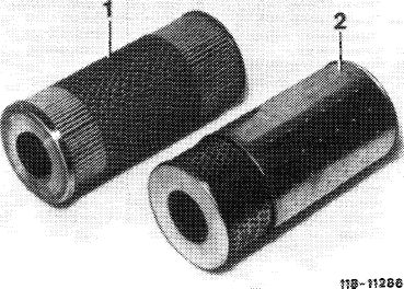
Main and bypass filter elements are contained in a cartridge.
During first inspection (1000-1500 km or 800-1000 miles) the initial operation oil filter element (1) should be replaced by the combination filter element (2).
|
 |
||
|
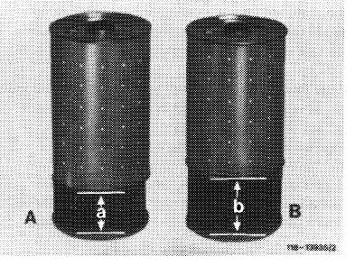
1 Initial operation filter element
2 Combination filter element
|
|||
|
|
|||
|
The combination filter element should then be replaced during oil change every 7500 km or 5000 miles.
Attention!
On this engine, install only the combination filter element (B), part No. 617 184 01 25 with the larger main flow filter component (dimension „b” = 55 mm).
|
 |
||
|
A Combination filter element Dimension A = 40 mm
B Combination filter element Dimension B = 55 mm
|
|||
|
|
|||
|
Operation
|
|||
|
|
|||
|
The oil filter comprises the following main components:
a) Oil filter housing with bypass, return flow locking valve and thermostat.
b) Cap with return flow pipe, check valve and sealing ring.
c) Combination filter element.
|
|||
|
|
|||
|
18.8-005/3 F 2
|
|||
|
|
|||
|
|
|||||||||||||||||||||||||||||||||||||||||||||||||||||||||||||||||||||||||||||||||||||||||||||||||||||||||||||||||||||||||||||||||||||||||||||||||||||||||||||||||||||
|
 |
||||||||||||||||||||||||||||||||||||||||||||||||||||||||||||||||||||||||||||||||||||||||||||||||||||||||||||||||||||||||||||||||||||||||||||||||||||||||||||||||||||
|
|
|||||||||||||||||||||||||||||||||||||||||||||||||||||||||||||||||||||||||||||||||||||||||||||||||||||||||||||||||||||||||||||||||||||||||||||||||||||||||||||||||||||
|
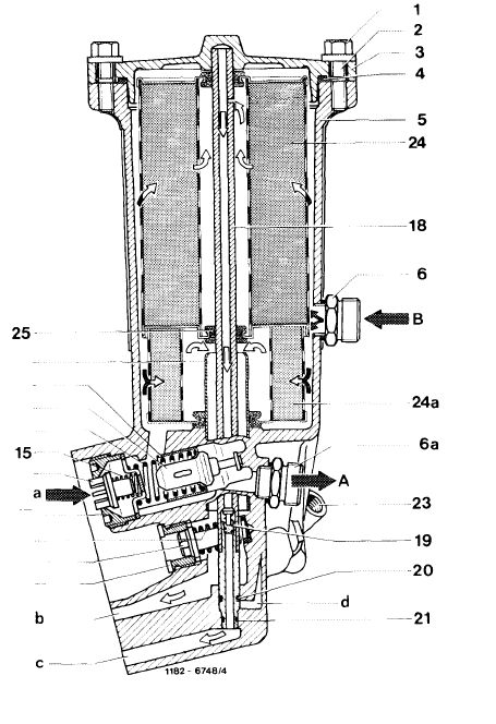
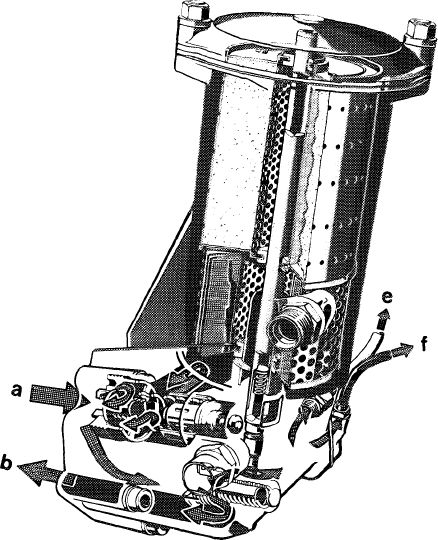
Coming from oil pump via feed duct (a), the oil enters the oil filter housing at return flow locking valve (16) and flows directly to combination filter element up to an oil temperature of approx. 110 °C.
After flowing through combination filter element the oil, which has been cleaned in main flow filter component (24a), flows via riser (22) and duct (b) to main oil duct and on to bearing points.
On the other hand, the oil, which has been finely filtered in bypass filter component (24) flows through return flow pipe (18) and duct (c) toward oil pan.
To make sure that main flow and bypass flow remain separated from each other, the combination filter element is provided with a rubber seal (25).
|
 |
||||||||||||||||||||||||||||||||||||||||||||||||||||||||||||||||||||||||||||||||||||||||||||||||||||||||||||||||||||||||||||||||||||||||||||||||||||||||||||||||||||
|
a From oil pump b To bearing points c Finely filtered oil toward oil pan
|
e To exhaust gas turbocharger f To oil pressure gage (models 116 and 123)
|
||||||||||||||||||||||||||||||||||||||||||||||||||||||||||||||||||||||||||||||||||||||||||||||||||||||||||||||||||||||||||||||||||||||||||||||||||||||||||||||||||||
|
|
|||||||||||||||||||||||||||||||||||||||||||||||||||||||||||||||||||||||||||||||||||||||||||||||||||||||||||||||||||||||||||||||||||||||||||||||||||||||||||||||||||||
|
18.8-005/4 F 2
|
|||||||||||||||||||||||||||||||||||||||||||||||||||||||||||||||||||||||||||||||||||||||||||||||||||||||||||||||||||||||||||||||||||||||||||||||||||||||||||||||||||||
|
|
|||||||||||||||||||||||||||||||||||||||||||||||||||||||||||||||||||||||||||||||||||||||||||||||||||||||||||||||||||||||||||||||||||||||||||||||||||||||||||||||||||||
|
|
|||
|
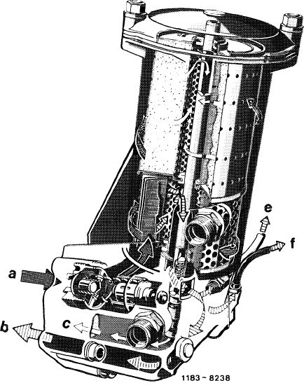
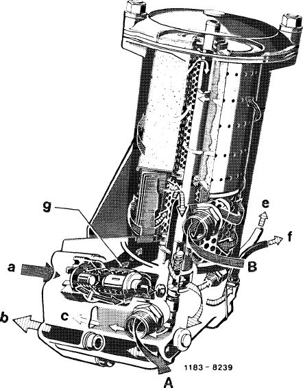
Starting at an oil temperature of approx. 110 °C the thermostat (11) starts to displace control valve (12), which arrives at its end position at approx. 125 °C. In end position, the direct flow toward combination filter element is locked except for a given quantity of oil (g). This quantity of oil is enough to guarantee lubrication of engine at low outside temperatures, when continuous flow in oil cooler is widely obstructed by viscous oil.
The larger oil quantity flows to air-oil cooler and is cooled there, it will then flow back to oil filter housing and flows through oil filter element from outside in inward direction.
|
|||
|
|
|||
|
The cleaned oil flows through riser (22) or return flow pipe (18) to bearing points or to oil pan.
Attention!
On engine 617.950 (model 116) a 95 °C thermostat has been installed in oil filter up to engine end No. 019718. Here, thermostat control starts at approx. 95 °C and ends at approx. 110 °C.
|
 |
||
|
A Uncleaned oil toward air-oil cooler
B Uncleaned oil from air-oil cooler
a From oil pump
b To bearing points
c Finely filtered oil toward oil pan
e To exhaust gas turbocharger
f To oil pressure gage (models 116 and 123)
g Oil quantity directly to combination filter element
|
|||
|
|
|||
|
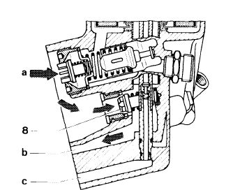
If the oil filter element is badly contaminated and the differential pressure between the contaminated side and the clean side of the filter exceeds 3.5 bar, bypass valve (8) will open. The oil will then flow uncleaned toward engine and exhaust gas turbo-charger.
|
1183 8257/1
|
||
|
8 Bypass valve a From oil pump b To bearing points
|
|||
|
|
|||
|
18.8-005/5 F 2
|
|||
|
|
|||
|
|
||||
|
Return flow locking valve (16) and check valve (19) in return flow pipe (18) prevent the oil from flowing out of oil filter back into oil pan with the engine stopped for an extended period.
|
 |
|||
|
a From oil pump
b To bearing points
e To exhaust gas turbocharger
f To oil pressure gage (models 116 and 123)
|
||||
|
1183-8240
|
||||
|
|
||||
|
When renewing oil filter element, unscrew cover (3) and pull up a bit.
The return flow pipe (18) attached to cap will then expose a bore which connects ducts (a) and (b) to each other. The oil in oil filter will flow through duct (c) into oil pan.
|
||||
|
|
||||
|
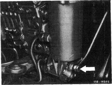
The exhaust gas turbocharger is provided with the oil required for lubrication and cooling by way of a line (arrow) on rear oil filter cover.
|
 |
|||
|
Models 116 and 123 (engines 617.950/952)
|
||||
|
|
||||
|
18.8-005/6 F 2
|
||||
|
|
||||
|
|
|||
|
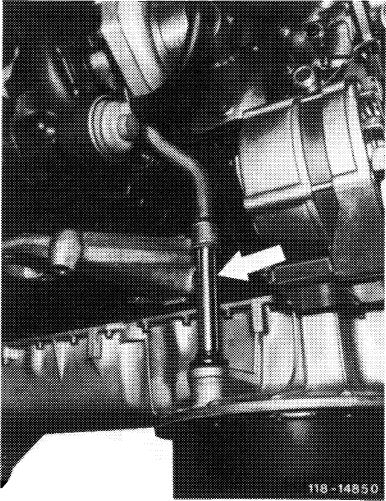
The oil return flow from exhaust gas turbocharger to oil pan proceeds at outside of engine (arrow).
|
 |
||
|
|
|||
|
18.8-005/7 F 2
|
|||
|
|
|||