Checking preglow system
|
|
|||
|
15—710 Checking preglow system
|
|||
|
|
|||
|
Conventional tools
|
|||
|
|
|||
|
Voltmeter (measuring range 0-3 volts/0—30 volts)
|
|||
|
|
|||
|
Note
|
|||
|
|
|||
|
Battery charged min. 60 % (acid density approx. 1.22 g/cc).
|
|||
|
|
|||
|
A. Engine 617.950 <®> up to 1980
|
|||
|
|
|||
 |
|||
|
|
|||
|
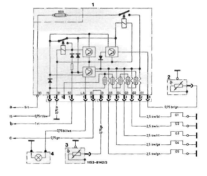
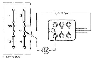
Wiring diagram
1 Preglow time relay
2 Temperature sensor preglow system
3 Temperature sensor, coolant
4 Preglow indicator lamp
|
G 1 – G 5 Pencil element glow plugs
a To cable connector terminal 30
b Relay air conditioning/starter terminal 50
c Plug instrument cluster jack 3
|
||
|
|
|||
|
15.8-710/1 F3
|
|||
|
|
|||
|
|
|||
|
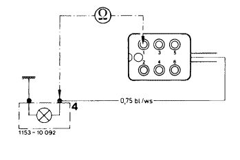
Checking main circuit of preglow system for interruption
In the event of an interruption:
Preglow indicator lamp will flash for approx. 30 seconds in key position „2 preglowing”.
|
|||
|
|
|||
|
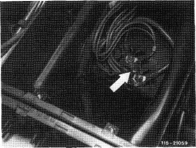
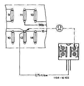
Test voltage at terminal 30 of preglow time relay against ground by means of voltmeter. If no voltage is indicated (approx. 12 volts), check red line from cable connector engine harness to preglow relay terminal 30 for interruption and remove interruption, if applicable.
|
 |
||
|
|
|||
|
If voltage is indicated, check 80-amps fuse for tight seat or for interruption, replace fuse.
If no faults have been found during tests, replace preglow time relay.
|
 |
||
|
|
|||
|
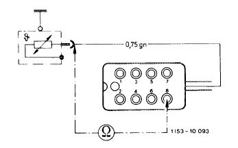
Testing glow bulb, temperature sensor of preglow system and their lines
In the event of an interruption:
Preglow indicator lamp not lighting up in spite of ready-to-start condition.
|
|||
|
|
|||
|
15.8-710/2 F 3
|
|||
|
|
|||
|
|
|||
|
Pull 6-point coupler from preglow relay, turn key to position „2”, bridge jack 1 and 2 of coupler.
|
 |
||
|
|
|||
|
If preglow indicator lamp is not lighting up, check glow bulb or renew, if required. If glow bulb is in order, test blue/white line from coupler jack 1 of preglow time relay to preglow indicator lamp for interruption, remove interruption.
|
 |
||
|
|
|||
|
If preglow indicator lamp lights up, test green line from 8-point coupler jack 8 of preglow time relay to temperature sensor for interruption, remove interruption.
If no interruption is found, test temperature sensor or renew, if required.
|
 |
||
|
|
|||
|
Resistance values of temperature sensor at coolant temperature:
0 °C = 8200 ft + 25 °C = 2440 ft + 80°C= 290 ft
If temperature sensor is in order, replace preglow time relay.
|
 |
||
|
|
|||
|
15.8-710/3 F 3
|
|||
|
|
|||
|
|
|||
|
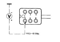
Testing activation of preglow time relay
|
|||
|
|
|||
|
In the event of an interruption:
Preglow indicator lamp not lighting up, engine cannot be started.
|
|||
|
|
|||
|
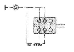
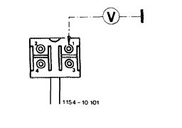
Pull 6-point coupler from preglow time relay, turn key into position „2”.
Test voltage at jack 2 (terminal 15) against ground by means of voltmeter.
|
 |
||
|
|
|||
|
If there is no voltage (approx. 12 volts) on red/black line from fuse box (terminal 15, non-fused side) to coupler jack 2 of preglow time relay for interruption and remove interruption, if required.
|
 |
||
|
|
|||
|
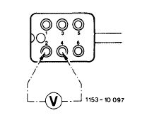
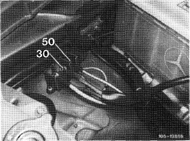
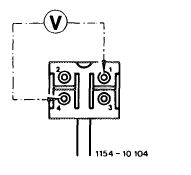
If voltage is indicated, connect voltmeter to jack 2 (terminal 15) and jack 4 (terminal 31) and test voltage.
If no voltage (approx. 12 volts) is indicated, test brown line from jack 4 to ground for interruption and remove interruption, if applicable.
If voltage is indicated, preglow time relay is defective. Replace preglow time relay.
|
 |
||
|
|
|||
|
15.8-710/4 F3
|
|||
|
|
|||
|
|
|||
|
Testing pencil element glow plugs and their lines
|
|||
|
|
|||
|
In the event of a complaint;
Preglow indicator lamp flashes approx. 30 seconds after a completed start or start attempt, the cause may be an interruption of a pencil element glow plug or a line to pencil element glow plugs of cylinder 1—5, or by a wrong current input of the pencil element glow plugs in cylinders 1—5.
Measure current input of pencil element glow plugs
with DC clip-on probe. For this purpose, place probe over
the individual lines on pencil element glow plugs.
Move key in steering lock to position „2”, the power input of each glow plug should then be 8—1 5 Amps, after 10-20 seconds.
At a value above 15 Amps., renew glow plug.
At a value below 8 Amps., test electric line or glow plug with ohmmeter for interruption.
Test for interruption:
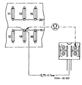
Pull 8-point coupler from preglow time relay.
|
 |
||
|
|
|||
|
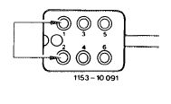
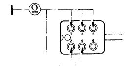
Measure resistance against ground (engine block) by means of ohmmeter one after the other at
jack 1 of coupler = pencil element glow plug cylinder 2 jack 2 of coupler = pencil element glow plug cylinder 1 jack 3 of coupler = pencil element glow plug cylinder 3 jack 5 of coupler = pencil element glow plug cylinder 4 jack 7 of coupler = pencil element glow plug cylinder 5.
|
 |
||
|
|
|||
|
If resistance « is measured, an interruption of respective pencil element glow plug or supply line or connection is indicated.
If a lower resistance (e.g. at 20 °C/68 °F<1 fl) is measured, the supply line and the pencil element glow plug are in order.
|
|||
|
|
|||
|
15.8-710/5 F3
|
|||
|
|
|||
|
|
||
|
B. Engine 617.95 standard and (us5> version starting 1981 (quick-start system)
|
||
|
|
||
 |
||
|
|
||
|
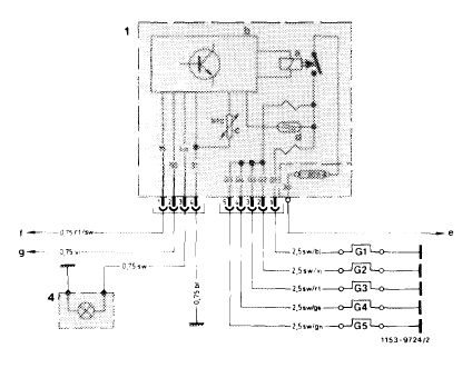
Wiring diagram
1 Preglow time relay
a Power relay
b Electronic unit
c Temperature sensor (NTC resistor)
d Reed relay
4 Preglow indicator lamp
e To cable connector engine harness
Terminal 30 in model 123
To point of support in fuse box
Terminal 30 in model 126 f To fuse box terminal 15
g To plug connection starter lockout and backup
lamp switch terminal 50 G 1 — G 5 Pencil element glow plugs
|
||
|
|
||
|
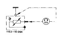
Testing glow bulb and its line
|
||
|
|
||
|
In the event of an interruption:
Preglow indicator lamp not lighting up when preglow system is switched on in spite of ready-to-start condition.
|
||
|
|
||
|
15.8-710/6 F 3
|
||
|
|
||
|
|
|||
|
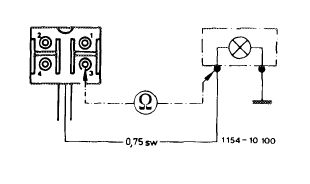
Pull 4-point coupler from preglow time relay, turn key into position „2”, bridge jack 1 and 3 of coupler.
If preglow indicator lamp is not lighting up, test glow bulb and renew, if required.
|
 |
||
|
|
|||
|
If glow bulb is in order, test black line from coupler jack 3 of preglow time relay to preglow indicator lamp for interruption, remove interruption.
|
 |
||
|
|
|||
|
If preglow indicator lamp lights up, preglow time relay is defective, replace preglow time relay.
|
|||
|
|
|||
|
Installation not concerning preglow time relay
If a preglow time relay has been stored in spare parts sector for a considerable period (refer to production date), the specified preglow time may be below specification after the relay has been installed, so that the engine will not start.
By preglowing several times one upon the other (5 — 10 times) the capacitor in preglow time relay is again activated and the specified preglow time is attained.
|
|||
|
|
|||
|
Testing main circuit of preglow system for interruption
|
|||
|
|
|||
|
In the event of an interruption:
Preglow indicator lamp not lighting up, engine cannot be started.
|
|||
|
|
|||
|
15.8-710/7 F 3
|
|||
|
|
|||
|
|
|||
|
Test voltage at terminal 30 of preglow time relay against ground by means of voltmeter.
If no voltage (approx. 12 volts) is indicated, test red line for interruption and remove interruption, if required.
|
 |
||
|
|
|||
|
115-20011/1
|
|||
|
|
|||
|
On model 126 from point of support terminal 30 to preglow time relay connection terminal 30.
|
 |
||
|
|
|||
|
On model 123 from cable connector engine harness terminal 30 to preglow time relay connection terminal 30.
If voltage is indicated, check 80-amps fuse for tight seat or interruption and replace, if required.
|
 |
||
|
|
|||
|
If no fault has been found up to now, test voltage on jack 1 of 4-point plug of preglow time relay against ground.
|
 |
||
|
|
|||
|
15.8-710/8 F 3
|
|||
|
|
|||
|
|
|||
|
If no voltage (approx. 12 volts) is indicated with preglow system switched on, test red/black line from fuse box terminal 15 to plug jack 1 of preglow time relay for interruption and remove interruption, if required.
|
|||
|
|
|||
|
On model 126 from input fuse No. 14 to plug jack 1 of preglow time relay.
|
 |
||
|
|
|||
|
On model 123 from input fuse No. 12 to plug jack 1 of preglow time relay.
|
 |
||
|
|
|||
|
If voltage is indicated, connect voltmeter to jack 1 (terminal 15) and jack 4 (terminal 31) and test voltage.
If no voltage (approx. 12 volts) is indicated, test brown line from jack 4 to ground for interruption and remove interruption, if required.
If no fault has been found up to now, the preglow time relay is defective. Replace preglow time relay.
|
 |
||
|
|
|||
|
15.8-710/9 F 3
|
|||
|
|
|||
|
|
|||
|
Testing pencil element glow plugs and their lines
In the event of an interruption:
Preglow indicator lamp not lighting up, engine fires poorly, an interruption of one or several pencil element glow plugs or lines to pencil element glow plugs may be indicated.
|
|||
|
|
|||
|
In the event of an interruption:
Preglow indicator lamp lights up, engine fires poorly after attaining ready-to-start condition, an interruption of a pencil element glow plug or a line to pencil element glow plugs of cylinder 2 to 5 or wrong current input of pencil element glow plugs in cylinder 1 to 5 may be indicated.
|
|||
|
|
|||
|
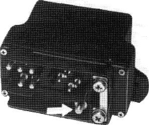
Measure power input of pencil element glow plugs with DC clip-on probe.
For this purpose, place probe over individual lines on pencil element glow plugs.
Move key in steering lock to position „2”, the power input of each glow plug should then be 8—15 Amps, after 10—20 seconds.
If the value is higher than 15 Amps., renew glow plug.
At a value below 8 Amps., test electric line or glow plug with ohmmeter for interruption.
Test for interruption:
Pull 6-point coupler from preglow time relay.
|
 |
||
|
Measure resistance against ground (engine block) with |__ __L _j11S4_10105
ohmmeter one after the other at
|
|||
|
|
|||
|
jack 1 of coupler = pencil element glow plug cylinder 1 jack 2 of coupler = pencil element glow plug cylinder 2 jack 3 of coupler = pencil element glow plug cylinder 3 jack 4 of coupler = pencil element glow plug cylinder 4 jack 5 of coupler = pencil element glow plug cylinder 5.
|
|||
|
|
|||
|
15.8-710/10 F 3
|
|||
|
|
|||
|
|
||
|
If resistance °° is measured, an interruption of the respective pencil element glow plug or supply line or connection is indicated.
If a smaller resistance (e.g. at 20 °C/68 °F < 1 12) is measured, the supply line and the pencil element glow plug are in order.
|
||
|
|
||
|
Note: It is possible that an indicator lamp (as the result of unfavorable tolerances) will indicate a fault only after a failure of 2 pencil element glow plugs in cylinders 2 to 5.
To make sure that the fault indication in preglow time relay is not defective, disconnect 2 pencil element glow plugs of cylinders 2 to 5 in such a case and repeat preglow operation.
|
||
|
|
||
|
If the indicator lamp is now indicating a fault (not lighting up) the preglow time relay is in order.
|
||
|
|
||
|
15.8-710/11 F3
|
||
|
|
||