Removal and installation of oil return flow line of exhaust gas turbocharger
|
|
|||
|
18—031 Removal and installation of oil return flow line of exhaust gas turbocharger
|
|||
|
|
|||
|
Note
|
 |
||
|
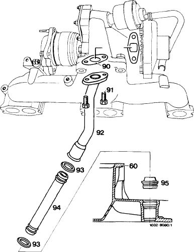
The return flow line consists of two line sections.
The upper line section (92) is screwed to exhaust gas turbocharger.
This line section holds the lower line section (94) which is sealed by means of an O-ring (93), which in turn is sealed by an O-ring (93) in contoured sealing ring (95) and is inserted with the latter in oil pan upper half (60).
|
|||
|
60 Oil pan upper half
90 Gasket
91 Hex. screws (2 each)
92 Upper line section
93 O-ring
94 Lower line section
95 Contoured sealing ring
|
|||
|
|
|||
|
Removal
|
|||
|
|
|||
|
1 Unscrew upper line section (92) from exhaust gas turbocharger.
2 Push upper line section down, pull outwards and remove.
3 Push lower line section (94) slightly down and force contoured sealing ring (95) out of oil pan.
|
|||
|
|
|||
|
18.8-031/1 F2
|
|||
|
|
|||
|
|
||
|
4 Pull out lower line section (94) in upward direction together with contoured sealing ring (95).
5 Check contoured sealing ring (95) and O-ring (93) for damage and porousity and replace, if required.
|
||
|
|
||
|
Installation
|
||
|
|
||
|
6 Insert contoured sealing ring (95) into oil pan (60).
7 Slip lower line section (94) into contoured sealing ring (95).
8 Insert upper line section (92) with a new gasket (90) and screw to exhaust gas turbocharger.
|
||
|
|
||
|
18.8-031/2 F2
|
||
|
|
||