Removal and installation of tensioning rail
|
|
|||||
|
05-330 Removal and installation of tensioning rail
|
|||||
|
|
|||||
|
Tightening torques
Nuts for cylinder head cover Closing plug for chain tensioner Necked-down screw for camshaft sprocket
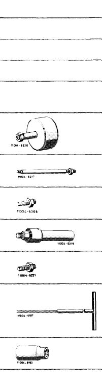
Special tools
Impact puller for bearing bolt (basic unit)
Threaded bolt M 8, 150 mm long for impact puller
Threaded bolt M 6, 50 mm long for impact puller
Puller for bearing bolt
Threaded bolt M 8, 30 mm long for puller
Screwdriver (Allen wrench) with tommy handle for hex. socket screws 6 mm, 440 mm long
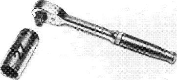
Socket 27 mm, 1/2″ square, for rotating engine
|
 |
Nm 15 90 80
116 589 20 33 00
616
 115 589 00 34 00
116
|
|||
|
|
|||||
|
Note
|
 |
||||
|
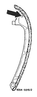
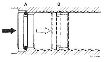
To avoid mixups with tensioning rail of 4-cylinder gasoline engines, the tensioning rails have been marked.
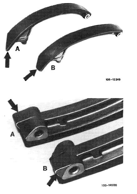
The tensioning rail of the 4-cylinder gasoline engine is wider at upper end (B) and has no bore in upper part (arrow).
|
|||||
|
|
|||||
|
05.8-330/1 F 2
|
|||||
|
|
|||||
|
|
|||||||||||||||||||||||||||||||||||||||
|
On the other hand, the tensioning rail of this engine is pointed at upper end (A) and has an 8 mm bore in upper part.
|
 |
||||||||||||||||||||||||||||||||||||||
|
A Tensioning rail diesel engines B Tensioning rail gasoline engines
|
|||||||||||||||||||||||||||||||||||||||
|
In addition, a lug has been cast-on to lower end of tensioning rail to avoid confusion.
The lug on the tensioning rail of this engine is located in direction of cylinder 1 and on tensioning rail of 4-cylinder gasoline engine in direction of balancing disk.
|
|||||||||||||||||||||||||||||||||||||||
|
A Tensioning rail diesel engines B Tensioning rail gasoline engines
|
|||||||||||||||||||||||||||||||||||||||
|
|
|||||||||||||||||||||||||||||||||||||||
|
In the periods June — August and September — October 1980 a tensioning rail made by another manufacturer has been installed.
This tensioning rail is not available as a spare part.
|
|||||||||||||||||||||||||||||||||||||||
|
|
|||||||||||||||||||||||||||||||||||||||
|
|||||||||||||||||||||||||||||||||||||||
|
|
|||||||||||||||||||||||||||||||||||||||
|
05.8-330/2 F 2
|
|||||||||||||||||||||||||||||||||||||||
|
|
|||||||||||||||||||||||||||||||||||||||
|
|
|||
|
Removal
|
 |
||
|
1 Remove radiator and fan.
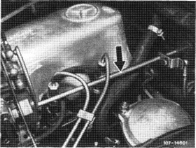
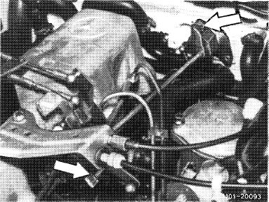
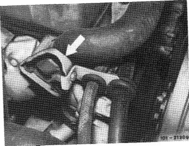
2 Disconnect regulating linkage to remove cylinder head cover. Pull out locking eye of longitudinal regulating shaft (arrow).
|
|||
|
Model 116.120
|
|||
|
|
|||
|
On models 116.120 and 123, pull longitudinal regulating shaft out of rubber mount in forward direction and remove in rearward direction.
On model 126.120, pull longitudinal regulating shaft out of guide lever in rearward direction and remove in forward direction.
|
 |
||
|
Model 123
|
|||
|
|
|||
|
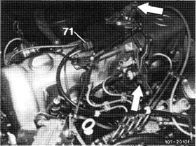
On models 123 with automatic transmission 722.303 (W 4 A 040) and 126.120, pull off central plug for vacuum lines (71) or vacuum lines. Disconnect Bowden wire, compress black plastic clip (arrow) and pull Bowden wire out of holder in rearward direction.
|
 |
||
|
Model 126.120
|
|||
|
|
|||
|
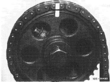
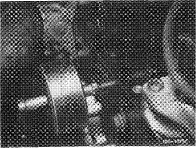
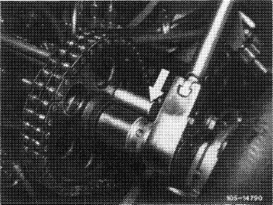
3 Remove pulley and vibration damper (03—340).
4 Rotate crankshaft with tool combination until recess in balancing disk is in front of bearing bolt of tensioning rail (Fig. item 12).
|
 |
||
|
|
|||
|
05.8-330/3 F 2
|
|||
|
|
|||
|
|
|||
|
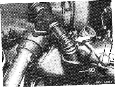
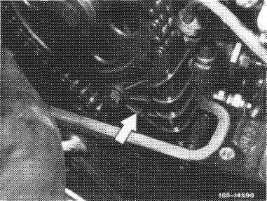
5 On engines with EGR ®. remove pipe line between EGR valve and exhaust manifold (arrow). For this purpose, unscrew shielding plate (10).
|
 |
||
|
|
|||
|
6 On model 123 with level control, unscrew line holder on thermostat housing (arrow).
|
 |
||
|
|
|||
|
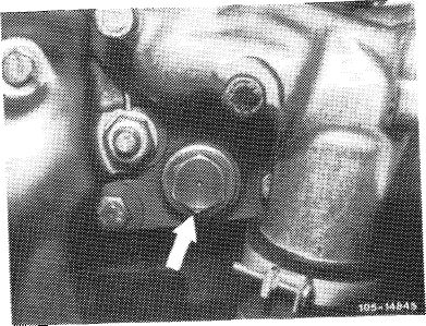
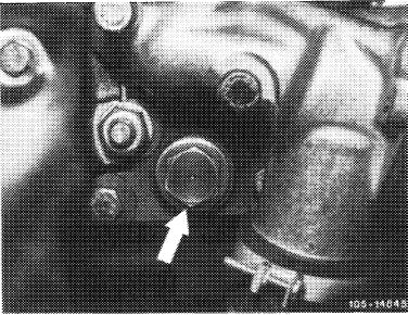
7 Unscrew closing plug of chain tensioner.
Attention!
The closing plug is under pressure of compression
|
 |
||
|
spring.
|
|||
|
|
|||
|
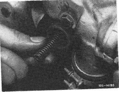
8 Remove compression spring in chain tensioner.
|
 |
||
|
|
|||
|
05.8-330/4 F 2
|
|||
|
|
|||
|
|
|||
|
9 Mark camshaft sprocket and timing chain in relation to each other.
|
 |
||
|
|
|||
|
10 Remove slide rail in cylinder head.
|
 |
||
|
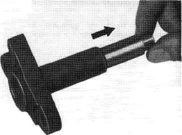
Pull out bearing bolt by means of impact puller.
|
|||
|
|
|||
 |
|||
|
|
|||
|
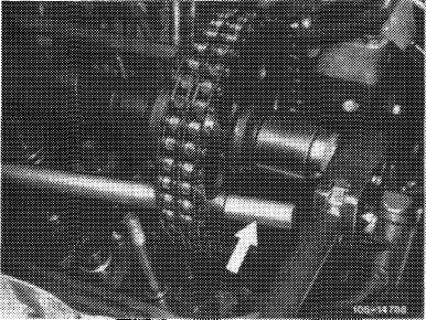
11 Remove camshaft sprocket.
For loosening necked-down screw, apply counterhold to camshaft sprocket by means of a screwdriver or steel bolt.
|
 |
||
|
|
|||
|
05.8-330/5 F 2
|
|||
|
|
|||
|
|
|||
|
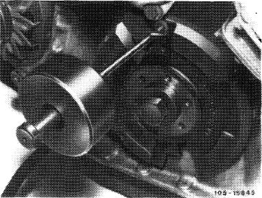
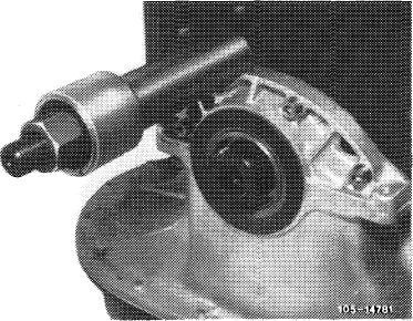
12 Knock out bearing bolt by means of impact puller.
|
 |
||
|
|
|||
|
Attention!
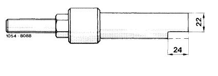
If bearing bolt is stuck to the extent that it cannot be knocked out with impact puller, use puller part No. 115 589 20 33 00.
For this purpose, remove balancing disk and provide puller with a recess.
The recess is necessary to position the puller with cylinder crankcase cover installed.
|
 |
||
|
|
|||
 |
|||
|
|
|||
|
13 Remove tensioning rail in upward direction.
14 Unscrew cyl. head screw M 8 in chain box adjacent to pressure bolt of chain tensioner by means of screwdriver (Allen wrench) with tommy handle.
15 Pull out pressure bolt of chain tensioner in inward direction (arrow).
16 Clean bearing bolt.
17 Renew badly worn tensioning rails and bearing bolts.
|
 |
||
|
|
|||
|
SQS-MTS?
|
|||
|
|
|||
|
05.8-330/6 F 2
|
|||
|
|
|||
|
|
|||
|
Installation
|
|||
|
|
|||
|
18 Coat bearing bolt on flange with sealing compound.
19 Position tensioning rail and knock in bearing bolt by means of impact puller.
20 Place camshaft sprocket with timing chain on camshaft, while paying attention to color marks.
|
|||
|
|
|||
|
21 Position necked-down screw for fastening camshaft sprocket and tighten to 80 Nm. For this purpose, apply counterhold to camshaft sprocket by means of a screwdriver or a steel bolt.
|
 |
||
|
|
|||
|
22 Place pressure bolt of chain tensioner on assembly detent.
|
 |
||
|
A Chain tensioner in assembly position B Chain tensioner in operating position
|
|||
|
|
|||
|
23 Insert compression spring.
24 Position closing plug of chain tensioner with new sealing ring and tighten to 90 Nm.
Make sure that pressure bolt is seated on thrust piece of tensioning rail.
25 Screw in cyl. head bolt M 8 by means of screwdriver (Allen wrench) with tommy handle.
26 For further installation proceed vice versa to removal.
|
 |
||
|
|
|||
|
05.8-330/7 F 2
|
|||
|
|
|||