Removal and installation of slide rails
|
|
|||||||||||||||||||||||||||||||||||||
|
05—340 Removal and installation of slide rails
|
|||||||||||||||||||||||||||||||||||||
|
|
|||||||||||||||||||||||||||||||||||||
|
|||||||||||||||||||||||||||||||||||||
|
|
|||||||||||||||||||||||||||||||||||||
|
Impact puller for bearing bolt (basic unit)
|
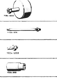 |
116 589 20 33 00
|
|||||||||||||||||||||||||||||||||||
|
Threaded bolt M 6, 150 mm long for impact puller
Threaded bolt M 6, 50 mm long for impact puller
Socket 27 mm, 1/2″ square, for rotating engine
|
116 589 02 34 00 116 589 01 34 00 001 589 65 09 00
|
||||||||||||||||||||||||||||||||||||
|
|
|||||||||||||||||||||||||||||||||||||
|
Remove slide rail (89)
|
 |
||||||||||||||||||||||||||||||||||||
|
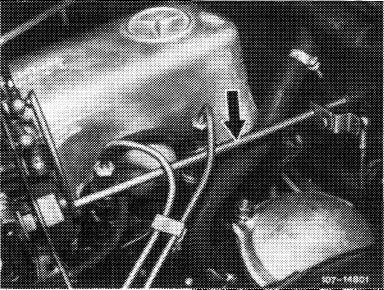
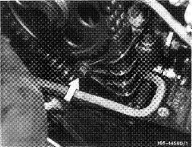
1 Disconnect regulating linkage to remove cylinder head cover. Pull out locking eye of longitudinal regulating shaft (arrow).
|
|||||||||||||||||||||||||||||||||||||
|
Model 116.120
|
|||||||||||||||||||||||||||||||||||||
|
|
|||||||||||||||||||||||||||||||||||||
|
On models 116.120 and 123, pull longitudinal regulating shaft out of rubber mount in forward direction and remove in rearward direction.
On model 126.120, pull longitudinal regulating shaft out of guide lever in rearward direction and remove in forward direction.
|
 |
||||||||||||||||||||||||||||||||||||
|
Model 123
|
|||||||||||||||||||||||||||||||||||||
|
|
|||||||||||||||||||||||||||||||||||||
|
05.8-340/1 F 2
|
|||||||||||||||||||||||||||||||||||||
|
|
|||||||||||||||||||||||||||||||||||||
|
|
|||
|
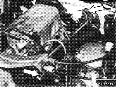
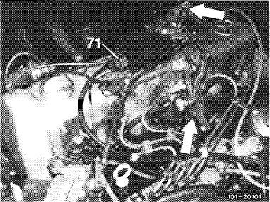
On models 123 with automatic transmission 722.303 (W 4 A 040) and 126.120, pull off central plug for vacuum lines (71) or vacuum lines. Disconnect Bowden wire, compress black plastic clip (arrow) and pull Bowden wire out of holder in rearward direction.
|
 |
||
|
Model 126.120
|
|||
|
|
|||
|
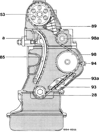
28 Crankshaft sprocket 53 Camshaft sprocket 85 Tensioning rail 89 Slide rail
93 Outer slide rail 93a Inner slide rail
94 Chain locking screw 98 Injection timer 98a Guide wheel
a Chain tensioner
|
 |
||
|
|
|||
|
2 On model 123 with level control, remove pressure oil pump with connected lines and put aside.
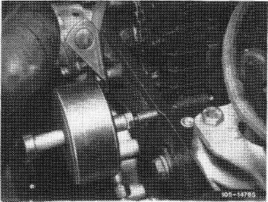
3 Remove screw (arrow).
|
 |
||
|
|
|||
|
05.8-340/2 F 2
|
|||
|
|
|||
|
|
|||
|
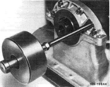
4 Pull out bearing bolt with impact puller.
5 Remove slide rail in upward direction.
|
 |
||
|
|
|||
|
Installation
|
|||
|
|
|||
|
6 Coat bearing bolt on flange with sealing compound.
7 Position slide rail and knock in bearing bolt by means of impact puller.
8 Screw-in screw.
9 Mount cylinder head cover.
|
|||
|
|
|||
|
Removing inner slide rail (93a)
|
|||
|
|
|||
|
1 Remove radiator and fan.
2 Remove vacuum pump (42—610).
3 Remove pulley, vibration damper and balancing disk (03-340).
4 Remove cylinder head cover (refer to Remove slide rail [89]).
|
|||
|
|
|||
|
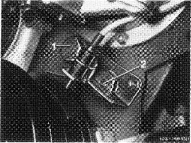
5 Unscrew closing plug (1) and put adjusting pointer with TDC transmitter aside.
6 Remove injection timer (07.1—210).
|
 |
||
|
|
|||
|
05.8-340/3 F 2
|
|||
|
|
|||
|
|
||||
|
7 Unscrew closing plug with upper bearing bolt (2) and pull out.
8 Pull out lower bearing bolt by means of impact puller.
9 Remove slide rail in upward direction.
|
 |
|||
|
|
||||
|
Installation
|
 |
tO5~137O?
|
||
|
10 Coat lower bearing bolt on flange with sealing compound.
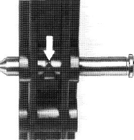
11 Position slide rail and knock in lower bearing bolt by means of impact puller.
Attention!
The locating lug of the slide rail should rest in locating groove of bearing bolt (arrow).
|
||||
|
|
||||
|
12 Position closing plug and screw-in.
|
||||
|
|
||||
|
13 Install injection timer (07.1-210).
|
||||
|
|
||||
|
14 Position adjusting pointer with TDC transmitter and screw on.
15 Attach vacuum pump (42—610).
16 Install pulley, vibration damper and balancing disk (03-340).
17 Install radiator and fan.
18 Mount cylinder head cover.
|
||||
|
|
||||
|
05.8-340/4 F 2
|
||||
|
|
||||
|
|
|||
|
Removing outer slide rail (93)
|
|||
|
|
|||
|
1 Remove radiator and fan.
2 Remove vacuum pump (42—610).
3 Remove injection timer (07.1—210).
4 Remove cylinder head cover (refer to Remove slide rail [89]).
|
|||
|
|
|||
|
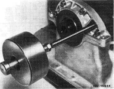
5 Pull out both bearing bolts of slide rail by means of impact puller.
6 Remove slide rail in upward direction.
|
 |
||
|
|
|||
|
Installation
|
 |
||
|
7 Coat both bearing bolts on flange with sealing compound.
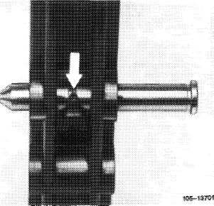
8 Position slide rail and knock in bearing bolts by means of impact puller.
Attention!
Locating lug of slide rail should rest in locating groove of lower bearing bolt (arrow).
|
|||
|
|
|||
|
9 Install injection timer (07.1-210).
10 Attach vacuum pump (42—610).
|
|||
|
|
|||
|
11 Install radiator and fan.
|
|||
|
|
|||
|
12 Mount cylinder head cover.
|
|||
|
|
|||
|
05.8-340/5 F 2
|
|||
|
|
|||
|
|
|||
|
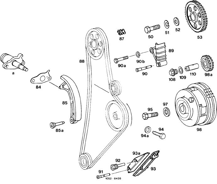
Timing chain, tensioning and slide rails
 |
|||
|
|
|||
|
50 Necked-down screw M 14 x 1.5 x 40
51 Snap ring B 14
52 Compensating washer
53 Camshaft sprocket 80 2 screws M 8 x 20
84 Gasket
85 Tensioning rail 85a Bearing bolt
87 Connecting link
88 Timing chain
89 Slide rail
90 Bearing bolt 90a Screw M 8 x 50 90b Snap ring A 8
|
91 3 bearing bolts
92 Closing plug with bearing bolt
93 Outer slide rail 93a Inner slide rail
94 Chain locking screw 94a Sealing ring A 12 x 17
95 Screw M 10×45
97 Washer
98 Injection timer 98a Guide wheel
108 Closing plug
109 Sealing ring
110 Shaft
a Chain tensioner
|
||
|
|
|||
|
05.8-340/6 F 2
|
|||
|
|
|||