Removal and installation of pulley, vibration damper and balancing disc
|
|
||||
|
03—340 Removal and installation of pulley, vibration damper and balancing disc
|
||||
|
|
||||
|
Tightening torques
Bolt M 18 x 1.5 x 45 on crankshaft Bolts M 8 x 30
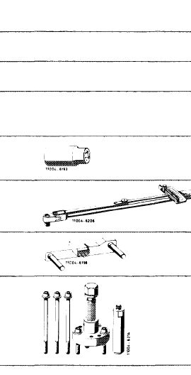
Special tools
Socket 27 mm, 1/2″ square
Torque wrench 150—500 Nm, 3/4″ square
Detent
|
 |
Nm
270-330
25
001 589 65 09 00 001 589 31 21 00 110 589 00 40 00
116 589 10 33 00
|
||
|
Puller for balancing disc
|
||||
|
|
||||
|
Conventional tool
|
||||
|
|
||||
|
Adaptor 3/4″ hex. socket to 1/2″ hex. head
|
e.g. made by Hazet, D-5630 Remscheid order no. 1058 R-1
|
|||
|
|
||||
|
Note
|
||||
|
|
||||
|
The vibration damper can be renewed without balancing.
When the balancing disc is renewed, static balancing is absolutely required (03—344).
Since January 1979, the fastening screws (17) for pulley and vibration damper on engine 617.950 are inserted without washers (18). On engines 617.951/ 952 from start of series.
|
||||
|
|
||||
|
03.8-340/1 F 2
|
||||
|
|
||||
|
|
||||||||||||||||||||||||||||||||||||||||||||||||||||||||||||||||||||||||||
|
Removal
|
 |
|||||||||||||||||||||||||||||||||||||||||||||||||||||||||||||||||||||||||
|
1 Remove radiator and fan.
|
||||||||||||||||||||||||||||||||||||||||||||||||||||||||||||||||||||||||||
|
2 Remove all V-belts (13-340).
|
||||||||||||||||||||||||||||||||||||||||||||||||||||||||||||||||||||||||||
|
3 Remove pulley and vibration damper.
|
||||||||||||||||||||||||||||||||||||||||||||||||||||||||||||||||||||||||||
|
||||||||||||||||||||||||||||||||||||||||||||||||||||||||||||||||||||||||||
|
|
||||||||||||||||||||||||||||||||||||||||||||||||||||||||||||||||||||||||||
|
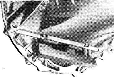
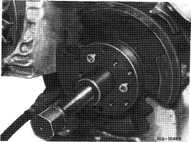
4 On models 116.120 and 123 with automatic transmission 722.120 (W4B 025), insert detent at flywheel as a couterhold when loosening screw in crankshaft.
|
 |
|||||||||||||||||||||||||||||||||||||||||||||||||||||||||||||||||||||||||
|
|
||||||||||||||||||||||||||||||||||||||||||||||||||||||||||||||||||||||||||
|
103-9243
|
||||||||||||||||||||||||||||||||||||||||||||||||||||||||||||||||||||||||||
|
|
||||||||||||||||||||||||||||||||||||||||||||||||||||||||||||||||||||||||||
|
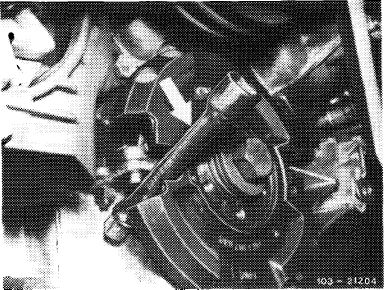
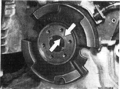
On models 126.120 and 123.with automatic transmission 722.303 (W4A 040) use a steel bolt as a counterhold in one of the recesses on balancing disc and on cylinder crankcase (arrow).
|
 |
|||||||||||||||||||||||||||||||||||||||||||||||||||||||||||||||||||||||||
|
|
||||||||||||||||||||||||||||||||||||||||||||||||||||||||||||||||||||||||||
|
03.8-340/2 F 2
|
||||||||||||||||||||||||||||||||||||||||||||||||||||||||||||||||||||||||||
|
|
||||||||||||||||||||||||||||||||||||||||||||||||||||||||||||||||||||||||||
|
|
|||
|
5 Remove screw on crankshaft.
|
 |
||
|
|
|||
|
6 Identify balancing disc and crankshaft by punch marks.
|
 |
||
|
|
|||
|
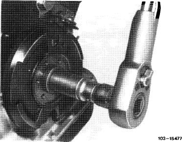
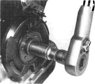
7 Pull off balancing disc by means of puller. For this purpose, place recess in balancing disc under water pump pulley.
Do not screw-in puller screws too far, since this might damage the radial sealing ring.
|
 |
||
|
|
|||
|
Installation
|
|||
|
|
|||
|
8 Place balancing disc on crankshaft in such a manner that the bores for the fitted pins are in alignment.
Note: The balancing disc is located on crankshaft by means of two offset fitted pins.
|
|||
|
|
|||
|
03.8-340/3 F 2
|
|||
|
|
|||
|
|
|||||
|
9 Mount balancing disc on crankshaft with screw M 18 x 1.5 x 45 and cup springs.
10 Knock-in both fitted pins.
|
 |
103-15477
|
|||
|
|
|||||
|
11 Mount the three cup springs with crown toward bolt head.
12 Lubricate bolt on crankshaft and tighten to 270—330 Nm, while applying counterhold to crankshaft with detent or steel bolt.
|
Z033- 4669/6
|
||||
|
|
|||||
|
13 Install vibration damper, pulley, fan and radiator.
|
|||||
|
|
|||||
|
14 Tension V-belt.
|
|||||
|
|
|||||
|
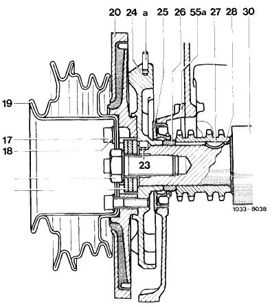
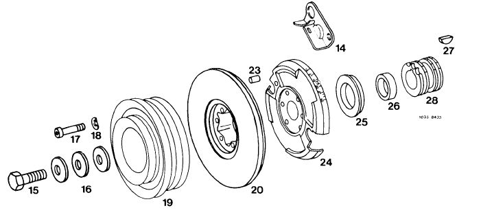
Pulley, vibration damper and balancing disc
|
|||||
|
|
|||||
|
14 Adjusting indicator
15 Bolt M 18 x 1.5 x45
16 Cup springs
17 6 bolts M 8×30
18 6 washers 8.4
19 Pulley
20 Vibration damper
23 2 fitted pins 8×8
24 Balancing disc
25 Radial sealing ring
26 Spacing ring
27 Woodruff key
28 Crankshaft gear (sprocket)
|
 |
||||
|
|
|||||
|
03.8-340/4 F 2
|
|||||
|
|
|||||