Removal and installation of intermediate sprocket shaft
|
|
||||||||||||||||||||||||||||||||||||||||||||||||||||||||||||
|
05—412 Removal and installation of intermediate sprocket shaft
|
||||||||||||||||||||||||||||||||||||||||||||||||||||||||||||
|
|
||||||||||||||||||||||||||||||||||||||||||||||||||||||||||||
|
||||||||||||||||||||||||||||||||||||||||||||||||||||||||||||
|
|
||||||||||||||||||||||||||||||||||||||||||||||||||||||||||||
|
Impact puller for bearing bolt (basic unit)
|
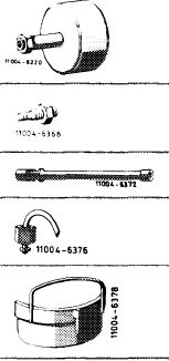 |
116 589 20 33 00
|
||||||||||||||||||||||||||||||||||||||||||||||||||||||||||
|
Threaded bolt M 6, 50 mm long for impact puller
|
116 589 01 34 00
|
|||||||||||||||||||||||||||||||||||||||||||||||||||||||||||
|
Articulated wrench
|
000 589 21 07 22
|
|||||||||||||||||||||||||||||||||||||||||||||||||||||||||||
|
Overflow pipe
|
636 589 02 23 00
|
|||||||||||||||||||||||||||||||||||||||||||||||||||||||||||
|
Holding plate
|
616 589 02 40 00
|
|||||||||||||||||||||||||||||||||||||||||||||||||||||||||||
|
|
||||||||||||||||||||||||||||||||||||||||||||||||||||||||||||
|
Note
|
 |
|||||||||||||||||||||||||||||||||||||||||||||||||||||||||||
|
The injection timer is mounted on intermediate sprocket shaft with a screw M 10 x 45 (95).
On engine 617.950 with double diaphragm vacuum pump, the screw has a hollow shaft.
The vacuum pump is provided with the required oil through this hollow screw.
|
||||||||||||||||||||||||||||||||||||||||||||||||||||||||||||
|
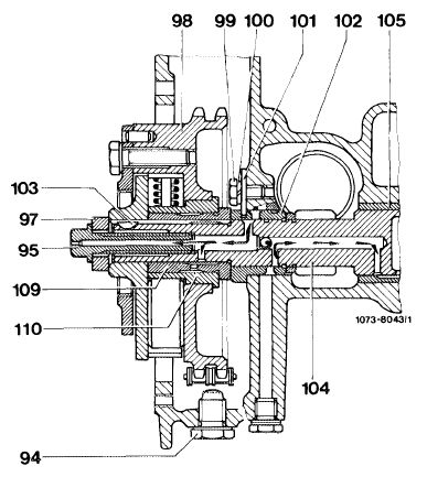
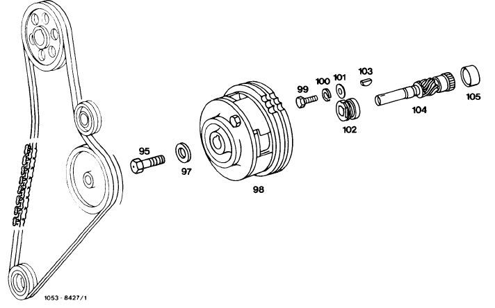
Layout of double diaphragm vacuum pump
94 Chain locking screw 101 Lock washer
95 Screw M 10 x 45 102 Bearing bushing front
97 Washer 103 Woodruff key
98 Injection timer 104 Intermediate sprocket shaft
99 Screw M 6 x 12 105 Bearing bushing rear
100 Snap ring B 6 109 Bearing bushing injection timer
|
||||||||||||||||||||||||||||||||||||||||||||||||||||||||||||
|
|
||||||||||||||||||||||||||||||||||||||||||||||||||||||||||||
|
05.8-412/1 F2
|
||||||||||||||||||||||||||||||||||||||||||||||||||||||||||||
|
|
||||||||||||||||||||||||||||||||||||||||||||||||||||||||||||
|
|
||||
|
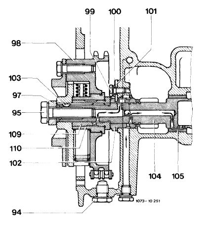
On engines with piston vacuum pump, screw (95) is not hollow.
Do not mix up screws (95).
|
 |
|||
|
Layout with piston vacuum pump
|
||||
|
94 Locking screw
95 Screw M 10 x 45
97 Washer
98 Injection timer
99 Screw M 6 x 12 100 Snap ring B 6
|
101 Lock washer
102 Bearing bushing front
103 Woodruff key
104 Intermediate sprocket shaft
105 Bearing bushing rear 109 Bearing bushing
|
|||
|
|
||||
|
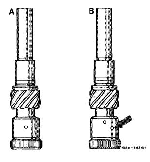
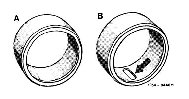
On engine 617.950 since August 1978, and on engines 617.951/952 since start of series, the intermediate sprocket shaft (B) and the rear bearing bushing (B) of engines 615, 616 and 617.912 are installed for reasons of standardization.
These parts can also be installed on engines 617.950 manufactured at an earlier date.
|
 |
|||
|
A Intermediate sprocket shaft 1st version B Intermediate sprocket shaft 2nd version
|
||||
|
|
||||
|
A Rear bearing bushing 1st version B Rear bearing bushing 2nd version
|
 |
|||
|
|
||||
|
05.8-412/2 F 2
|
||||
|
|
||||
|
|
|||
|
Removal
1 Remove fan and radiator shell.
2 Remove vacuum pump (42—610).
3 Remove injection timer (07.1-210).
4 Remove injection pump (07.1 — 180).
5 Pull out intermediate sprocket shaft toward the rear.
|
|||
|
|
|||
|
Installation
|
|||
|
|
|||
|
6 Insert intermediate sprocket shaft from the rear.
7 Install injection timer (07.1—210).
8 Install injection pump (07.1 — 180).
9 Check timing of camshaft (05—215) and begin of delivery (injection timing) of injection pump (07.1-110).
10 Install vacuum pump (42-610).
11 Install fan and radiator shell.
|
|||
|
|
|||
|
Intermediate sprocket shaft and injection timer
|
|||
|
|
|||
 |
|||
|
|
|||
|
95 Screw M 10 x 45
97 Washer
98 Injection timer
99 Screw M 6 x 12 100 Snap ring B 6
|
101 Lock washer
102 Bearing bushing front
103 Woodruff key
104 I ntermediate sprocket shaft
105 Bearing bushing rear
|
||
|
|
|||
|
05.8-412/3 F2
|
|||
|
|
|||