Removal and installation of guide wheel
|
|
|||||||||||||||||||||||||||||||||||||
|
05—440 Removal and installation of guide wheel
|
|||||||||||||||||||||||||||||||||||||
|
|
|||||||||||||||||||||||||||||||||||||
|
|||||||||||||||||||||||||||||||||||||
|
|
|||||||||||||||||||||||||||||||||||||
|
Impact puller for bearing bolt (basic unit)
|
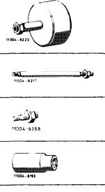 |
116 589 20 33 00
616 589 00 34 00 116 589 01 34 00 001 589 65 09 00
|
|||||||||||||||||||||||||||||||||||
|
Threaded bolt M 8, 150 mm long for impact puller
Threaded bolt M 6, 50 mm long for impact puller
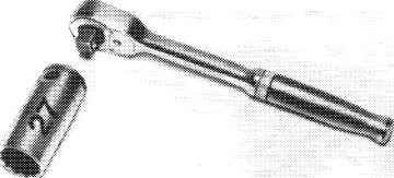
Socket 27 mm, 1/2″ square, for rotating engine
|
|||||||||||||||||||||||||||||||||||||
|
|
|||||||||||||||||||||||||||||||||||||
|
Note
|
|||||||||||||||||||||||||||||||||||||
|
|
|||||||||||||||||||||||||||||||||||||
|
If, on model 123 with level control, the rear bearing bushing for guide wheel shaft requires renewal, make sure that the bearing bushing on basic bore projects by 1 mm. Do not install bushing flush.
|
|||||||||||||||||||||||||||||||||||||
|
|
|||||||||||||||||||||||||||||||||||||
|
Removal
|
 |
||||||||||||||||||||||||||||||||||||
|
1 On model 123 with level control, unscrew pressure oil pump with lines connected and put aside.
|
|||||||||||||||||||||||||||||||||||||
|
|
|||||||||||||||||||||||||||||||||||||
|
05.8-440/1 F 2
|
|||||||||||||||||||||||||||||||||||||
|
|
|||||||||||||||||||||||||||||||||||||
|
|
|||
|
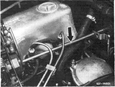
2 Disconnect regulating linkage to remove cylinder head cover. Pull out locking eye of longitudinal regulating shaft (arrow).
|
 |
||
|
Model 116.120
|
|||
|
|
|||
|
On models 116.120 and 123, pull longitudinal regulating shaft out of rubber mount in forward direction and remove in rearward direction.
On model 126.120, pull longitudinal regulating shaft out of guide lever in rearward direction and remove in forward direction.
|
 |
||
|
Model 123
|
|||
|
|
|||
|
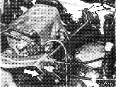
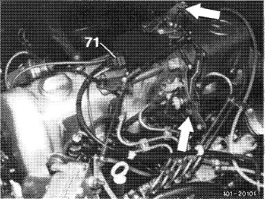
On models 123 with automatic transmission 722.303 (W 4 A 040) and 126.120, pull out central plug for vacuum lines (71) or vacuum lines. Disconnect Bowden wire, compress black plastic clip (arrow) and pull Bowden wire out of holder in rearward direction.
|
 |
||
|
Model 126.120
|
|||
|
|
|||
|
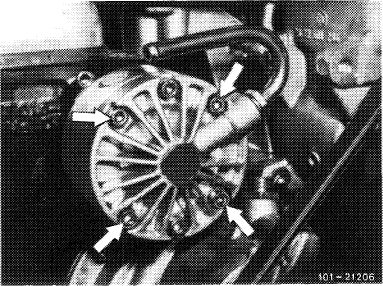
3 Set crankshaft to ignition TDC.
For this purpose, rotate crankshaft by means of tool combination.
|
 |
||
|
|
|||
|
05.8-440/2 F 2
|
|||
|
|
|||
|
|
|||
|
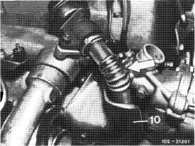
4 On engines with EGR (usa), remove pipe line between EGR valve and exhaust manifold (arrow). Unscrew shielding plate (10) for this purpose.
|
 |
||
|
|
|||
|
5 Unscrew closing plug of chain tensioner.
Attention!
Closing plug is under pressure of compression spring.
|
 |
||
|
|
|||
|
6 Remove compression spring in chain tensioner.
|
 |
||
|
|
|||
|
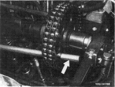
7 Mark camshaft sprocket and timing chain in relation to each other.
|
 |
||
|
|
|||
|
05.8-440/3 F 2
|
|||
|
|
|||
|
|
|||
|
8 Remove slide rail in cylinder head.
|
 |
||
|
Pull out bearing bolt by means of impact puller.
|
|||
|
|
|||
 |
|||
|
|
|||
|
9 Remove camshaft sprocket.
For loosening necked-down screw, apply counterhold to camshaft sprocket by means of a screwdriver or steel bolt.
|
 |
||
|
|
|||
|
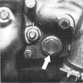
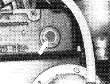
10 On engines 617.950/951, unscrew closing plug (arrow).
|
 |
||
|
|
|||
|
05.8-440/4 F 2
|
|||
|
|
|||
align=”top”>
|
|
|||||||||||||||||||||||||||||||||||||
|
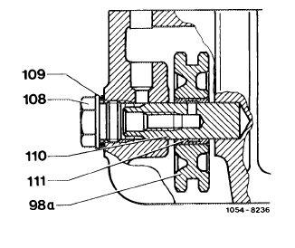
11 Pull out shaft (110) by means of impact puller and remove guide wheel (98a) in upward direction.
|
 |
||||||||||||||||||||||||||||||||||||
|
98a Guide wheel
108 Closing plug
109 Sealing ring
110 Shaft
|
|||||||||||||||||||||||||||||||||||||
|
|
|||||||||||||||||||||||||||||||||||||
 |
|||||||||||||||||||||||||||||||||||||
|
|
|||||||||||||||||||||||||||||||||||||
|
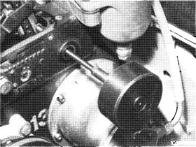
12 On model 123 with level control, unscrew locking screw of front bearing bushing (arrow).
Pull out shaft together with bearing bushing and remove guide wheel.
|
 |
||||||||||||||||||||||||||||||||||||
|
|
|||||||||||||||||||||||||||||||||||||
|
05—440 Removal and installation of guide wheel
|
|||||||||||||||||||||||||||||||||||||
|
|
|||||||||||||||||||||||||||||||||||||
|
|||||||||||||||||||||||||||||||||||||
|
|
|||||||||||||||||||||||||||||||||||||
|
Impact puller for bearing bolt (basic unit)
|
|
116 589 20 33 00
616 589 00 34 00 116 589 01 34 00 001 589 65 09 00
|
|||||||||||||||||||||||||||||||||||
|
Threaded bolt M 8, 150 mm long for impact puller
Threaded bolt M 6, 50 mm long for impact puller
Socket 27 mm, 1/2″ square, for rotating engine
|
|||||||||||||||||||||||||||||||||||||
|
|
|||||||||||||||||||||||||||||||||||||
|
Note
|
|||||||||||||||||||||||||||||||||||||
|
|
|||||||||||||||||||||||||||||||||||||
|
If, on model 123 with level control, the rear bearing bushing for guide wheel shaft requires renewal, make sure that the bearing bushing on basic bore projects by 1 mm. Do not install bushing flush.
|
|||||||||||||||||||||||||||||||||||||
|
|
|||||||||||||||||||||||||||||||||||||
|
Removal
|
|
||||||||||||||||||||||||||||||||||||
|
1 On model 123 with level control, unscrew pressure oil pump with lines connected and put aside.
|
|||||||||||||||||||||||||||||||||||||
|
|
|||||||||||||||||||||||||||||||||||||
|
05.8-440/1 F 2
|
|||||||||||||||||||||||||||||||||||||
|
|
|||||||||||||||||||||||||||||||||||||
|
|
|||||||||||||||||||||||||||||||||||||
|
2 Disconnect regulating linkage to remove cylinder head cover. Pull out locking eye of longitudinal regulating shaft (arrow).
|
|
||||||||||||||||||||||||||||||||||||
|
Model 116.120
|
|||||||||||||||||||||||||||||||||||||
|
|
|||||||||||||||||||||||||||||||||||||
|
On models 116.120 and 123, pull longitudinal regulating shaft out of rubber mount in forward direction and remove in rearward direction.
On model 126.120, pull longitudinal regulating shaft out of guide lever in rearward direction and remove in forward direction.
|
|
||||||||||||||||||||||||||||||||||||
|
Model 123
|
|||||||||||||||||||||||||||||||||||||
|
|
|||||||||||||||||||||||||||||||||||||
|
On models 123 with automatic transmission 722.303 (W 4 A 040) and 126.120, pull out central plug for vacuum lines (71) or vacuum lines. Disconnect Bowden wire, compress black plastic clip (arrow) and pull Bowden wire out of holder in rearward direction.
|
|
||||||||||||||||||||||||||||||||||||
|
Model 126.120
|
|||||||||||||||||||||||||||||||||||||
|
|
|||||||||||||||||||||||||||||||||||||
|
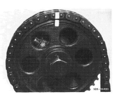
3 Set crankshaft to ignition TDC.
For this purpose, rotate crankshaft by means of tool combination.
|
|
||||||||||||||||||||||||||||||||||||
|
|
|||||||||||||||||||||||||||||||||||||
|
05.8-440/2 F 2
|
|||||||||||||||||||||||||||||||||||||
|
|
|||||||||||||||||||||||||||||||||||||
|
|
|||||||||||||||||||||||||||||||||||||
|
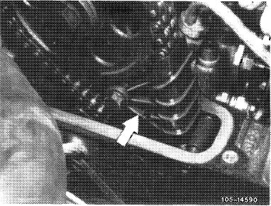
4 On engines with EGR (usa), remove pipe line between EGR valve and exhaust manifold (arrow). Unscrew shielding plate (10) for this purpose.
|
|
||||||||||||||||||||||||||||||||||||
|
|
|||||||||||||||||||||||||||||||||||||
|
5 Unscrew closing plug of chain tensioner.
Attention!
Closing plug is under pressure of compression spring.
|
|
||||||||||||||||||||||||||||||||||||
|
|
|||||||||||||||||||||||||||||||||||||
|
6 Remove compression spring in chain tensioner.
|
|
||||||||||||||||||||||||||||||||||||
|
|
|||||||||||||||||||||||||||||||||||||
|
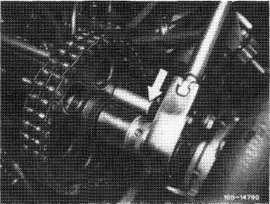
7 Mark camshaft sprocket and timing chain in relation to each other.
|
|
||||||||||||||||||||||||||||||||||||
|
|
|||||||||||||||||||||||||||||||||||||
|
05.8-440/3 F 2
|
|||||||||||||||||||||||||||||||||||||
|
|
|||||||||||||||||||||||||||||||||||||
|
|
|||||||||||||||||||||||||||||||||||||
|
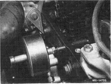
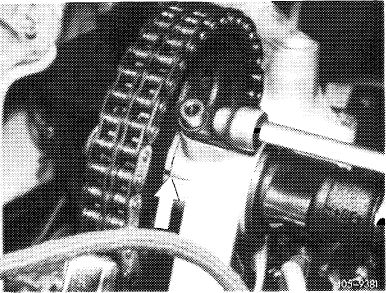
8 Remove slide rail in cylinder head.
|
|
||||||||||||||||||||||||||||||||||||
|
Pull out bearing bolt by means of impact puller.
|
|||||||||||||||||||||||||||||||||||||
|
|
|||||||||||||||||||||||||||||||||||||
|
|
|||||||||||||||||||||||||||||||||||||
|
|
|||||||||||||||||||||||||||||||||||||
|
9 Remove camshaft sprocket.
For loosening necked-down screw, apply counterhold to camshaft sprocket by means of a screwdriver or steel bolt.
|
|
||||||||||||||||||||||||||||||||||||
|
|
|||||||||||||||||||||||||||||||||||||
|
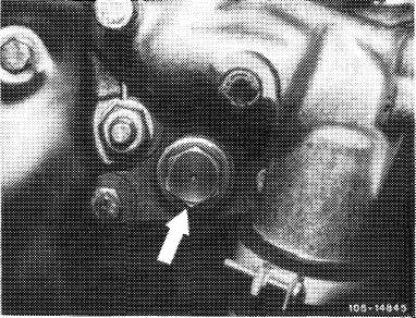
10 On engines 617.950/951, unscrew closing plug (arrow).
|
|
||||||||||||||||||||||||||||||||||||
|
|
|||||||||||||||||||||||||||||||||||||
|
05.8-440/4 F 2
|
|||||||||||||||||||||||||||||||||||||
|
|
|||||||||||||||||||||||||||||||||||||
|
|
|||||||||||||||||||||||||||||||||||||
|
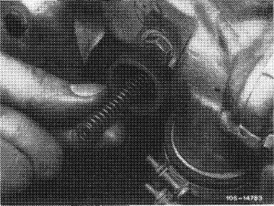
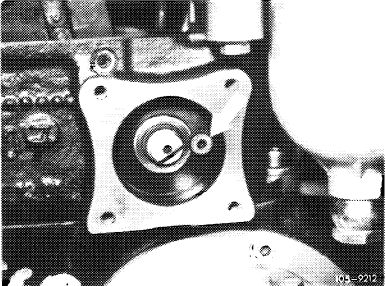
11 Pull out shaft (110) by means of impact puller and remove guide wheel (98a) in upward direction.
|
|
||||||||||||||||||||||||||||||||||||
|
98a Guide wheel
108 Closing plug
109 Sealing ring
110 Shaft
|
|||||||||||||||||||||||||||||||||||||
|
|
|||||||||||||||||||||||||||||||||||||
|
|
|||||||||||||||||||||||||||||||||||||
|
|
|||||||||||||||||||||||||||||||||||||
|
12 On model 123 with level control, unscrew locking screw of front bearing bushing (arrow).
Pull out shaft together with bearing bushing and remove guide wheel.
|
|
||||||||||||||||||||||||||||||||||||
|
|
|||||||||||||||||||||||||||||||||||||
|
Installation
|
|||||||||||||||||||||||||||||||||||||
|
|
|||||||||||||||||||||||||||||||||||||
|
13 Position guide wheel and slip in shaft.
On model 123 with level control, screw in bearing bushing locking screw (arrow in Fig. item 12).
14 Screw in closing plug with new sealing ring.
|
|||||||||||||||||||||||||||||||||||||
|
|
|||||||||||||||||||||||||||||||||||||
|
05.8-440/5 F 2
|
|||||||||||||||||||||||||||||||||||||
|
|
|||||||||||||||||||||||||||||||||||||
|
|
|||||||||||||||||||||||||||||||||||||
|
On model 123 with level control, screw on pressure oil pump with new gasket.
15 Mount camshaft sprocket, while paying attention to color marks.
Tighten necked-down screw to 80 Nm. For this purpose, apply counterhold to camshaft sprocket by means of a screwdriver or steel bolt.
|
 |
||||||||||||||||||||||||||||||||||||
|
|
|||||||||||||||||||||||||||||||||||||
|
16 Install slide rail.
|
|||||||||||||||||||||||||||||||||||||
|
|
|||||||||||||||||||||||||||||||||||||
|
17 Rotate crankshaft and check adjusting mark in TDC position of engine.
|
 |
||||||||||||||||||||||||||||||||||||
|
|
|||||||||||||||||||||||||||||||||||||
|
18 Insert compression spring into chain tensioner and tighten closing plug to 90 Nm.
19 On engines with EGR (@), install shielding plate and pipe line (Fig. item 4).
20 Mount cylinder head cover.
|
 |
||||||||||||||||||||||||||||||||||||
|
|
|||||||||||||||||||||||||||||||||||||
|
05.8-440/6 F 2
|
|||||||||||||||||||||||||||||||||||||
|
|
|||||||||||||||||||||||||||||||||||||
|
|
|||||||||||||||||||||||||||||||||||||
|
Installation
|
|||||||||||||||||||||||||||||||||||||
|
|
|||||||||||||||||||||||||||||||||||||
|
13 Position guide wheel and slip in shaft.
On model 123 with level control, screw in bearing bushing locking screw (arrow in Fig. item 12).
14 Screw in closing plug with new sealing ring.
|
|||||||||||||||||||||||||||||||||||||
|
|
|||||||||||||||||||||||||||||||||||||
|
05.8-440/5 F 2
|
|||||||||||||||||||||||||||||||||||||
|
|
|||||||||||||||||||||||||||||||||||||
|
|
|||
|
On model 123 with level control, screw on pressure oil pump with new gasket.
15 Mount camshaft sprocket, while paying attention to color marks.
Tighten necked-down screw to 80 Nm. For this purpose, apply counterhold to camshaft sprocket by means of a screwdriver or steel bolt.
|
|
||
|
|
|||
|
16 Install slide rail.
|
|||
|
|
|||
|
17 Rotate crankshaft and check adjusting mark in TDC position of engine.
|
|
||
|
|
|||
|
18 Insert compression spring into chain tensioner and tighten closing plug to 90 Nm.
19 On engines with EGR (@), install shielding plate and pipe line (Fig. item 4).
20 Mount cylinder head cover.
|
|
||
|
|
|||
|
05.8-440/6 F 2
|
|||
|
|
|||