Removal and installation of flywheel and driven plate
|
|
||||||||||||||||||||||||||||||||||||||||
|
03—410 Removal and installation of flywheel and driven plate
|
||||||||||||||||||||||||||||||||||||||||
|
|
||||||||||||||||||||||||||||||||||||||||
|
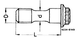
Necked-down screws
|
||||||||||||||||||||||||||||||||||||||||
|
|
||||||||||||||||||||||||||||||||||||||||
|
Part no.
|
110 990 04 19
|
|||||||||||||||||||||||||||||||||||||||
|
|
||||||||||||||||||||||||||||||||||||||||
|
Thread dia. D
|
M 10x 1
|
 |
||||||||||||||||||||||||||||||||||||||
|
when new
|
7.7-0.2
|
|||||||||||||||||||||||||||||||||||||||
|
Necked-down stem dia. d
|
minimum dia. 7.3
|
|||||||||||||||||||||||||||||||||||||||
|
|
||||||||||||||||||||||||||||||||||||||||
|
||||||||||||||||||||||||||||||||||||||||
|
|
||||||||||||||||||||||||||||||||||||||||
|
Angle of rotation tool
|
 |
116 589 01 13 00
|
||||||||||||||||||||||||||||||||||||||
|
|
||||||||||||||||||||||||||||||||||||||||
|
Detent
|
 |
110 589 00 40 00
|
||||||||||||||||||||||||||||||||||||||
|
|
||||||||||||||||||||||||||||||||||||||||
|
Note
|
 |
|||||||||||||||||||||||||||||||||||||||
|
If a new flywheel is installed, set new wheel to balancing condition of removed wheel (03—440).
|
||||||||||||||||||||||||||||||||||||||||
|
|
||||||||||||||||||||||||||||||||||||||||
|
03.8-410/1 F2
|
||||||||||||||||||||||||||||||||||||||||
|
|
||||||||||||||||||||||||||||||||||||||||
|
|
|||||||||
|
” „vwheel with
|
°f
|
 |
|||||||
|
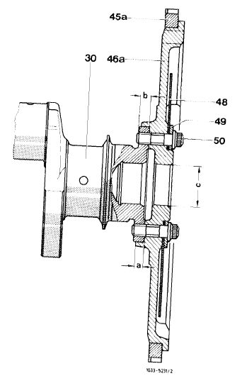
Engine 110: dimension a = 4.5
|
mm
|
||||||||
|
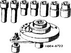
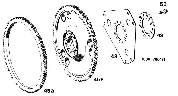
Layout flywheel and driven plate 30 Crankshaft
|
|||||||||
|
45a Ring gear 46a Flywheel
|
b J° mm C 5 mm dia–
|
||||||||
|
48 Driven plate
49 Spacing washer
50 Necked-down screw
|
|||||||||
|
|
|||||||||
|
Removal
|
|||||||||
|
|
|||||||||
|
1 Remove transmission.
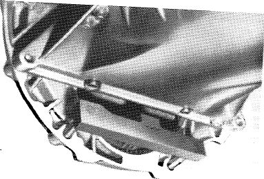
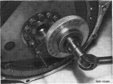
2 On models 116.120 and 123 with automatic trans miRslrtn 722120 <W4B 025), position
|
 |
||||||||
|
|
|||||||||
|
one of (arrow)3
|
recesses on balancing disc for counter-
|
 |
|||||||
|
|
Crankcase
|
|
|||||||
|
03.8-410/2 F 2
|
|||||||||
|
|
|||||||||
|
|
||||
|
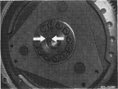
3 Loosen necked-down screws. Remove flywheel, driven plate and spacing washer.
Note: The flywheel and crankshaft are identified by a mark (arrows).
|
 |
|||
|
|
||||
|
Installation
|
||||
|
|
||||
|
4 Measure necked-down stem dia. „d” of necked-down screws.
If the minimum dia. has been attained, replace necked-down screws.
5 Position flywheel, driven plate and spacing washer on crankshaft journal in such a manner that the marks are in alignment.
|
||||
|
|
||||
|
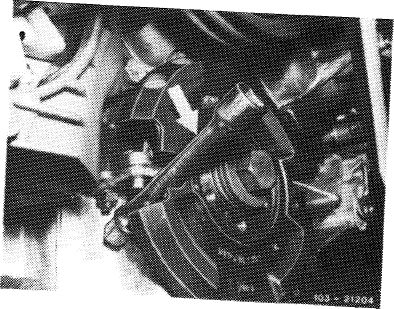
6 Lubricate necked-down screws, screw-in and tighten to 30-40 Nm.
7 Tighten to angle of rotation torque of 90—100° by means of angle of rotation tool.
|
 |
|||
|
|
||||
|
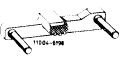
Flywheel and driven plate
|
 |
|||
|
45a Ring gear
46a Flywheel
48 Driven plate
49 Spacing washer
50 12 necked-down screws
|
||||
|
|
||||
|
03.8-410/3 F2
|
||||
|
|
||||