Removal and installation of crankshaft sprocket
|
|
||||
|
03—350 Removal and installation of crankshaft sprocket
|
||||
|
|
||||
|
Tightening torques
|
Nm
|
|||
|
|
||||
|
Bolt M 18 x 1.5 x 45 to crankshaft
|
270-330
|
|||
|
|
||||
|
Nuts for cylinder head cover
|
15
|
|||
|
|
||||
|
Oil pan upper half to cylinder crankcase
|
||||
|
|
||||
|
10
|
||||
|
|
||||
|
Oil pan lower half to upper half
|
||||
|
|
||||
|
Engine carrier to engine mount front
|
70
|
|||
|
|
||||
|
Necked-down screw for camshaft sprocket
|
80
|
|||
|
|
||||
|
Special tools
|
||||
|
|
||||
|
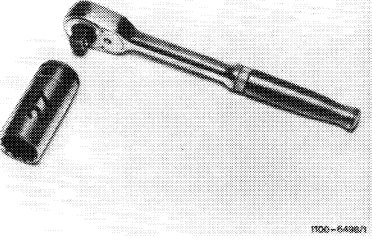
Torque wrench 150—500 Nm 3/4″ square
|
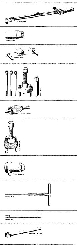 |
001 589 31 21 00
|
||
|
Socket 27 mm, 1/2″ square
|
001 589 65 09 00
|
|||
|
Detent
|
110 589 00 40 00
|
|||
|
Puller for balancing disc
|
116 589 10 33 00
|
|||
|
Puller for spacing ring
|
616 589 00 33 00
|
|||
|
Puller for crankshaft sprocket
|
615 589 01 33 00
|
|||
|
Installer for radial sealing ring
|
130 589 00 61 00
|
|||
|
Screwdriver (Allen wrench) with tommy handle for hex. socket screws 5 mm, 300 mm long.
|
116 589 02 07 00
|
|||
|
|
|
|||
|
|
||||
|
03.8-350/1 F 2
|
||||
|
|
||||
|
|
||||
|
Sleeve for centering front cylinder crankcase cover and oil pan
|
 |
617 589 00 14 00
|
||
|
|
||||
|
Conventional tools
|
||||
|
|
||||
|
Engine hoist (Motordirigent) size 1.5
|
e.g. made by Backer, D-5630 Remscheid order no. 3178
|
|||
|
|
||||
|
Adaptor 3/4″ square socket to 1/2″ square head
|
e.g. made by Hazet, D-5630 Remscheid order nor. 1058 R-1
|
|||
|
|
||||
|
Removal
|
 |
|||
|
1 Remove radiator and fan.
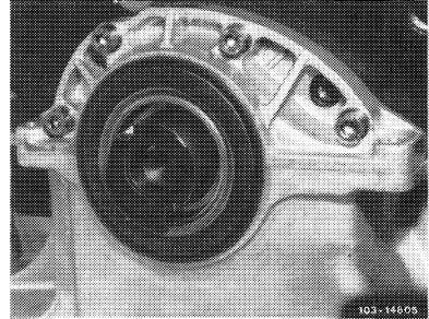
2 Remove pulley, vibration damper and balancing disc (03-340).
|
||||
|
3 Completely remove oil pan (01—310). On model 126.120, remove engine.
|
||||
|
|
||||
|
4 Remove front crankshaft radial sealing ring (03-324).
5 Remove front cylinder crankcase housing cover (01-215).
|
 |
|||
|
|
||||
|
03.8-350/2 F 2
|
||||
|
|
||||
|
|
|||
|
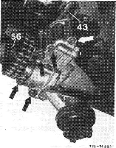
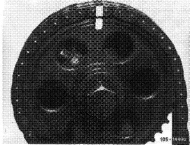
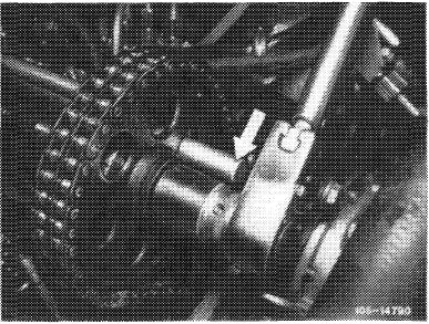
6 Unscrew fastening screw (56) of oil pump sprocket (Fig. item 9).
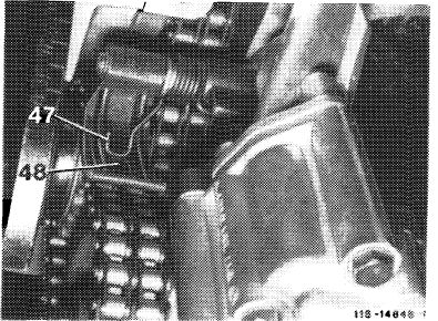
7 Remove torsion spring (47) from clamp (48) toward the rear.
8 Turn clamp in upward direction.
|
 |
||
|
47 Torsion spring
48 Clamp
|
|||
|
|
|||
|
9 Remove sprocket by means of two screw-drivers.
|
 |
||
|
10 Remove sprocket.
|
|||
|
11 Remove double roller chain of oil pump.
|
|||
|
43 Flange member 56 Fastening bolt
|
|||
|
|
|||
|
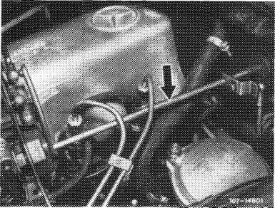
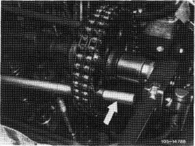
12 Disconnect regulating linkage to remove cylinder head cover. Pull out locking eye of longitudinal regulating shaft (arrow).
On models 116.120 and 123, pull longitudinal regulating shaft out of rubber mount in forward direction and remove in rearward direction.
|
 |
||
|
Model 116.120
|
|||
|
|
|||
|
03.8-350/3 F 2
|
|||
|
|
|||
|
|
|||
|
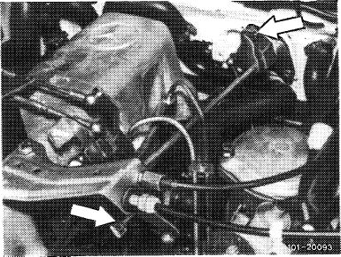
On model 126.120, pull longitudinal regulating shaft out of guide lever in rearward direction and remove in forward direction.
|
 |
||
|
Model 123
|
|||
|
|
|||
|
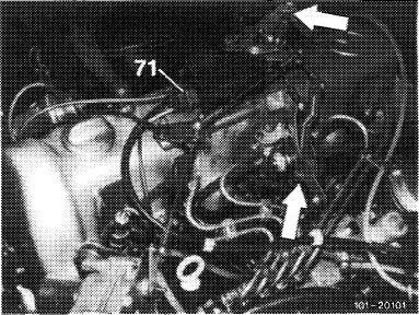
On models 123 with automatic transmission 722.303 (W4A040) and 126.120, pull out central plug for vacuum lines (71) or vacuum lines. Disconnect bowden wire, compress black plastic clip (arrow) and pull bowden wire out of holder in rearward direction.
|
 |
||
|
Model 126.120
|
|||
|
|
|||
|
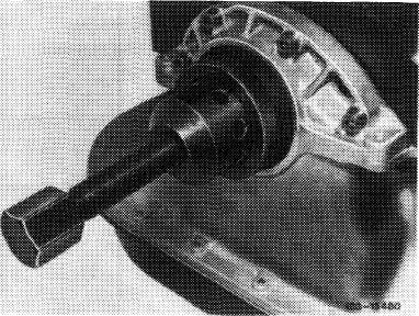
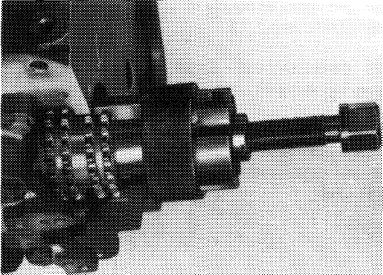
13 Set engine to TDC of 1st cylinder. For this purpose, screw bolt M 18 x 1.5 x 45 with cup washers into crankshaft.
Rotate engine with tool combination at crankshaft.
Attention!
Rotate crankshaft only in direction of rotation of engine.
|
 |
||
|
|
|||
|
14 Mark camshaft and crankshaft sprocket with paint in relation to timing chain.
15 Remove chain tensioner (05—310).
|
 |
||
|
|
|||
|
03.8-350/4 F 2
|
|||
|
|
|||
|
|
|||
|
16 Remove camshaft sprocket.
To loosen necked-down screw, apply counterhold to camshaft sprocket by means of a screwdriver or steel bolt, loosen holder for fuel lines and swivel sideways.
17 Remove timing chain from teeth of crankshaft sprocket.
|
 |
||
|
|
|||
|
18 Unscrew bolt M 18 x 1.5 x 45.
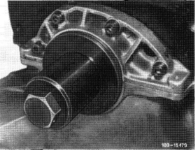
19 Pull off spacing ring by means of puller.
|
 |
||
|
|
|||
|
20 Pull off crankshaft sprocket by means of puller.
|
 |
||
|
|
|||
|
Installation
|
|||
|
|
|||
|
21 Transfer color mark from old crankshaft sprocket to new sprocket.
22 Heat crankshaft sprocket on a hot plate (approx. 80 °C) and slip on crankshaft.
|
|||
|
|
|||
|
03.8-350/5 F 2
|
|||
|
|
|||
|
|
|||
|
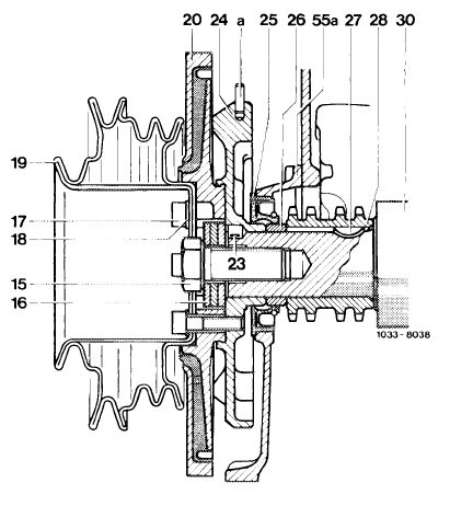
23 Knock spacing ring on crankshaft.
24 Insert timing chain and place camshaft sprocket on camshaft. Pay attention to color code.
|
|||
|
|
|||
|
25 Position necked-down screw for attaching camshaft sprocket and tighten to 80 Nm. For this purpose, apply counterhold to camshaft sprocket by means of a screwdriver or steel bolt.
26 Place double roller chain of oil pump on crankshaft sprocket.
27 Place oil pump sprocket into double roller chain and then slip on drive shaft. Screw-in fastening screw.
|
 |
||
|
|
|||
|
28 Set clamp on double roller chain and torsion spring on clamp.
29 Completely install oil pan. For centering of oil pan, slip sleeve on crankshaft journal.
30 Coat front cylinder crankcase housing cover on flange surfaces with sealing compound and position against cylinder crankcase. Screw-in oil pan bolts first (01-215).
|
|||
|
|
|||
|
31 Install front crankshaft radial sealing ring (03-324).
32 Install pulley, vibration damper and balancing disc (03-340).
33 Rotate engine with tool combination and check adjusting marks.
34 Install chain tensioner (05—310).
35 For further installation proceed vice versa to removal.
|
 |
||
|
|
|||
|
03.8-350/6 F 2
|
|||
|
|
|||