Removal and installation of engine (oil capacity)
|
|
|||||
|
01—030 Removal and installation of engine (oil capacity)
|
|||||
|
|
|||||
|
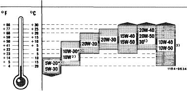
Specified viscosity classes according to SAE during constant outside temperatures
|
|||||
|
|
|||||
|
1) During constant outside temperatures above + 30 °C
( + 86 F) SAE 40 may be used.
2) Do not use.
3) All season oil
4) For oil types which are identified on pages 226.1 and 227.1 of Specifications for Service Products with footnote l), the following applies:
SAE 5W-20 below + 10 °C
SAE 10W-30 in temperate zones all-year.
|
 |
||||
|
|
|||||
|
Attention!
Do not use single range oil grades of viscosity class SAE 10 for this engine.
|
|||||
|
|
|||||
|
Oil capacity in liters (for approved engine oil grades refer to Specifications for Service Products)
|
|||||
|
|
|||||
|
Engine (total capacity during initial filling)
|
8.5
|
||||
|
|
|||||
|
Tightening torques
|
Nm
|
||||
|
|
|||||
|
Oil drain plug to oil pan
|
40
|
||||
|
|
|||||
|
Nuts for oil filter cover
|
20-25
|
||||
|
|
|||||
|
Bolts for engine carrier on engine mount front
|
70
|
||||
|
|
|||||
|
Special tools
|
|||||
|
|
|||||
|
Tester for cooling system and closing radiator
|
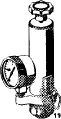 |
001 589 48 21 00
|
|||
|
|
|||||
|
Radiator cap with hose for leak test
|
 |
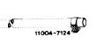 |
605 589 00 25 00
|
||
|
|
|||||
|
Syringe for removing oil
|
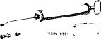 |
112 589 00 72 00
|
|||
|
|
|||||
|
01.8-030/1 F2
|
|||||
|
|
|||||
|
|
|||
|
Conventional tool
|
|||
|
|
|||
|
Engine hoist (Motordirigent) size 1.5
|
e.g. made by Backer, D-5630 Remscheid order no. 3178
|
||
|
|
|||
|
Note
|
|||
|
|
|||
|
Remove and install engine with transmission.
|
|||
|
|
|||
|
Removal
|
 |
||
|
1 Completely drain coolant.
|
|||
|
Drain plug on cylinder crankcase
|
|||
|
|
|||
|
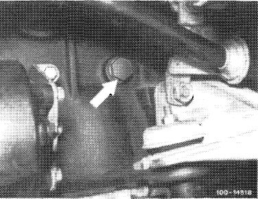
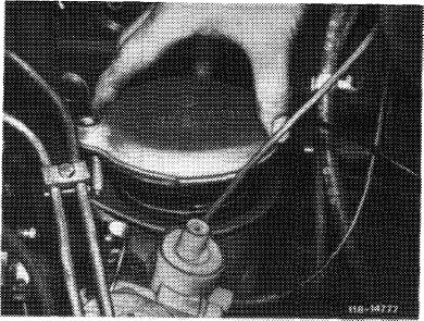
2 On model 116.120, remove engine hood. On models 123 and 126.120 move engine hood into 90 ° position and engage detent lever (arrow).
3 Remove radiator and fan cover.
4 Remove viscofan coupling with fan.
|
 |
||
 |
|||
|
|
|||
|
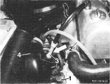
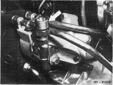
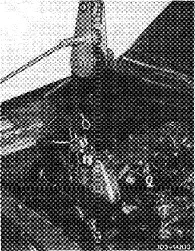
5 Remove air cleaner with intake line (4). For this purpose, pull off engine vent line (3) and on model 116.120 with double diaphragm vacuum pump, pull off vacuum line (2) and cable on temperature switch (1).
|
 |
||
|
1 Temperature switch 100 C
2 Vacuum line
3 Vent line
4 Intake line
|
|||
|
|
|||
|
01.8-030/2 F2
|
|||
|
|
|||
|
|
|||
|
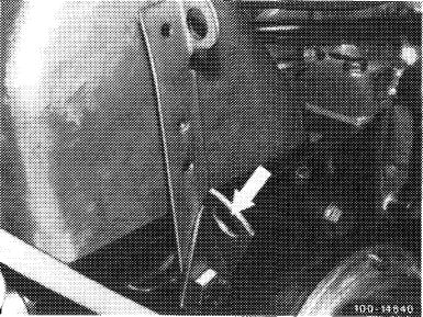
6 Disconnect regulating linkage.
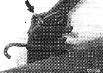
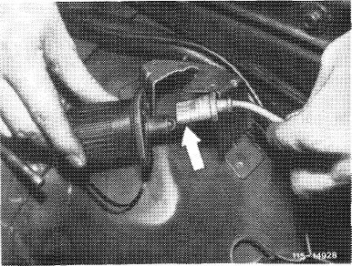
7 Remove longitudinal regulating shaft while pulling out locking eye (arrow).
|
 |
||
|
Model 116.120
|
|||
|
|
|||
|
On models 116.120 and 123, pull longitudinal regulating shaft out of rubber mount in forward direction and remove in rearward direction.
|
 |
||
|
Model 123
|
|||
|
|
|||
|
On model 126.120, pull longitudinal regulating shaft out of guide lever in rearward direction and remove in forward direction.
|
 |
||
|
Model 126.120
|
|||
|
|
|||
|
8 Unscrew oil filter cover and pull up slightly.
9 Draw oil from reservoir of power-steering pump and disconnect hoses.
|
 |
||
|
|
|||
|
01.8-030/3 F2
|
|||
|
|
|||
|
|
|||
|
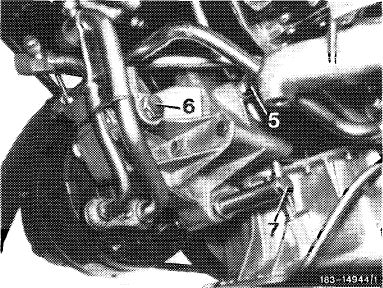
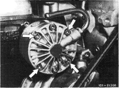
10 On model 116.120, remove refrigerant compressor with lines connected and put aside. For this purpose, unscrew 3 screws (5, 6 and 7).
|
 |
||
|
|
|||
|
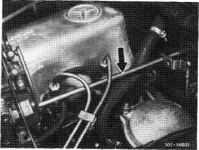
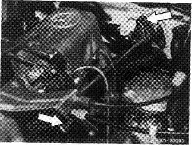
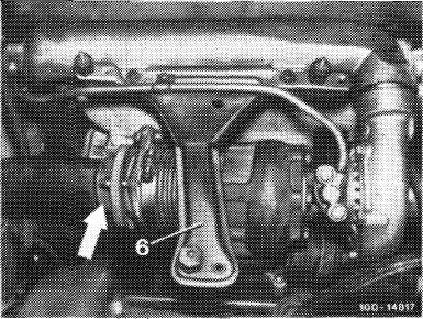
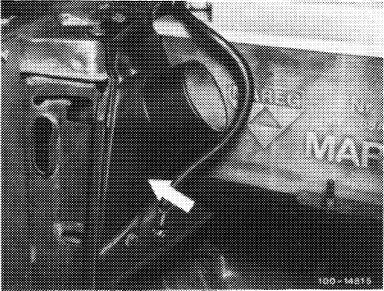
On models 123 and 126.120, drain air conditioning system and unscrew lines (arrows).
11 Disconnect heating water hoses.
12 Disconnect fuel and vacuum lines.
|
 |
||
|
|
|||
 |
|||
|
|
|||
|
13 Pull cable harness for pencil element glow plugs from preglow relay.
14 Disconnect coolant temperature indicator.
|
 |
||
|
|
|||
|
01.8-030/4 F 2
|
|||
|
|
|||
|
|
|||
|
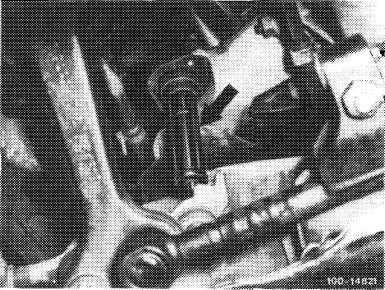
15 Disconnect TDC transmitter on test socket. Unscrew test socket for this purpose.
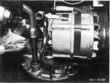
16 Pull cable plug from alternator.
17 Disconnect cable to starter on battery and on cable connector.
18 Unscrew oil pressure gauge on oil filter.
|
 |
||
|
|
|||
|
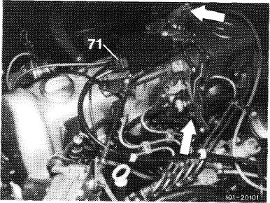
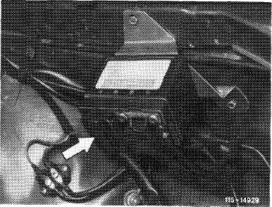
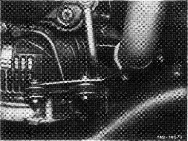
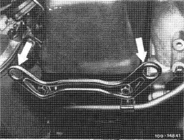
19 On model 123 with level control, unscrew hydraulic oil pump with lines connected and put aside. For this purpose, just loosen screws (arrows).
|
 |
||
|
|
|||
|
20 Unscrew exhaust on exhaust gas turbocharger.
|
 |
||
|
|
|||
|
21 Unscrew exhaust lateral support on transmission.
22 Disconnect ground connecting cable on body.
23 Unscrew bolts for engine carrier on engine mount from below.
|
 |
||
|
|
|||
|
01.8-030/5 F2
|
|||
|
|
|||
|
|
|||
|
24 Unscrew both engine shock absorbers on frame cross member or console for lower contro arm.
25 Remove shielding plate in range of universal shaft intermediate bearing.
26 Loosen clamping nut of universal shaft.
27 Unscrew universal shaft on transmission.
|
 |
||
|
|
|||
|
28 Loosen all connections and pull off selector rod on transmission.
29 Remove rear engine carrier with engine mount.
30 Attach ropes of engine hoist to suspension eyes.
|
 |
||
|
Suspension eye front
|
|||
|
|
|||
|
Suspension eyes rear
|
 |
||
|
|
|||
|
01.8-030/6 F 2
|
|||
|
|
|||
|
|
|||
|
31 Lift out engine with transmission in a diagonal position of approx. 45°.
|
 |
||
|
Installation
|
|||
|
Attention!
When installing a new engine following previous bearing damage, flush oil cooler and oil hoses.
32 Check engine mounts, engine shock absorber, oil, coolant and fuel hoses and renew, if required.
|
|||
|
|
|||
|
33 Install engine and connect.
34 Screw-on universal shaft and adjust (41—020).
35 On model 116.120 unscrew intake scoop for inserting righthand holding spring (driving direction) on radiator.
36 Check all drain plugs for tight seat.
|
 |
||
|
|
|||
|
37 Add oil and coolant.
38 Check coolant for antifreeze (20-010).
39 Pressure-test cooling system with tester.
40 Clean air filter elements or renew.
41 Adjust idle speed (07.1-100).
42 On model 123, adjust engine stop (22-220).
|
|||
|
|
|||
|
01.8-030/7 F 2
|
|||
|
|
|||