Engine breather – functional description
|
|
||||
|
01—040 Engine breather — functional description
|
||||
|
|
||||
|
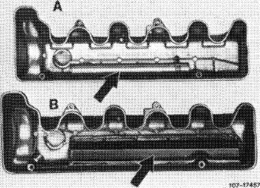
A. Standard version, (usa) Federal up to 1980, <©> California up to 1979, © starting 1981, (T)starting 1982
|
||||
|
|
||||
|
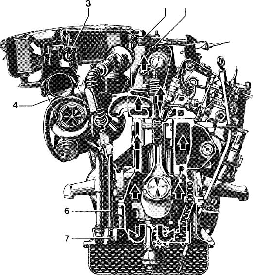
This engine has a closed, service-free crankcase breathing system.
The engine blow-by gases and cylinder crankcase vapors flow through vent pipe (1) and connection (2) on cylinder head cover to intake line (4) in front of compressor.
From here, they are flowing into combustion chambers together with the intake air.
A bypass line (5) is located between clean air end of air filter and breather line.
|
2 1
1074-8047/2
|
|||
|
|
||||
|
By means of this line, the compressor can draw up clean air at high speeds in addition to blow-by gases and vapors.
|
||||
|
|
||||
|
The additional intake of clean air will restrict the
vacuum in cylinder crankcase.
|
||||
|
|
||||
|
1 2 4 5
|
Vent pipe Connection Intake line Bypass line
|
|||
|
|
||||
|
Blow-by gases Fresh air
|
||||
|
|
||||
|
For @) Federal 1980 the vent pipe (A) screwed to inside of cylinder head cover has been replaced by a vent plate (B) which is riveted-on and sealed with silicone rubber. As a result, the volume of the oil separating space (damping chamber) has been enlarged.
This cylinder head cover is mounted as standard equipment and for CD from start of series.
|
 |
|||
|
|
||||
|
01.8-040/1 F2
|
||||
|
|
||||
|
|
||||
|
B. (usa) Federal starting 1981, © California starting 1980
|
||||
|
|
||||
|
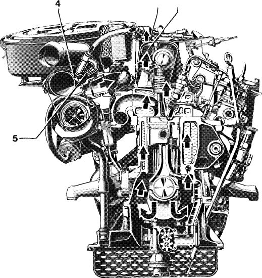
The complete engine breathing system requires no maintenance.
The engine blow-by gases and cylinder crankcase vapors are flowing via vent plate (1), which is revited to cylinder head cover, and connection (2) to cyclonic oil separator (3), which is located in air cleaner housing.
From there, they are flowing by way of the intake line (4) in front of compressor and together with the intake air into the combustion chambers.
|
||||
|
|
||||
|
The oil separated in cyclonic oil separator (3) flows through return line (6) and check valve (7) installed in oil pan upper half toward oil pan. The check valve prevents that the vacuum in intake system will draw oil vapors out of oil pan.
2 1
1004-9042/1
|
||||
|
|
||||
|
1
2 3 4 6 7
|
Vent plate Connection Oil separator Intake line Return line Check valve
Fresh air Blow-by gases
|
|||
|
|
||||
|
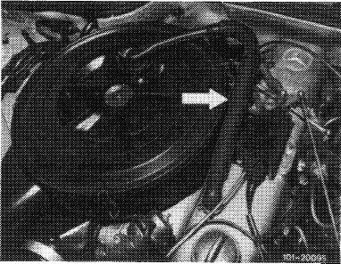
Starting model year 1981, the vent line between cylinder head cover and air cleaner has been changed from oval to round for better flow characteristics (arrow).
|
 |
|||
|
|
||||
|
01.8-040/2 F 2
|
||||
|
|
||||