Checking and correcting adjustment of TDC transmitter
|
|
|||||||||||||||||||||||||||||||||||||||||||||||||||||||||||
|
03—345 Checking and correcting adjustment of TDC transmitter
|
|||||||||||||||||||||||||||||||||||||||||||||||||||||||||||
|
|
|||||||||||||||||||||||||||||||||||||||||||||||||||||||||||
|
|||||||||||||||||||||||||||||||||||||||||||||||||||||||||||
|
|
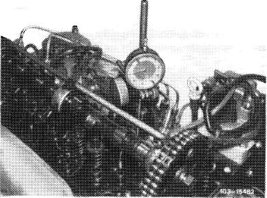
|||||||||||||||||||||||||||||||||||||||||||||||||||||||||||
|
’) 0.05 mm higher during lasting outside temperatures below —20 °C.
|
|||||||||||||||||||||||||||||||||||||||||||||||||||||||||||
|
|
|||||||||||||||||||||||||||||||||||||||||||||||||||||||||||
|
Tightening torque
|
Nm
|
||||||||||||||||||||||||||||||||||||||||||||||||||||||||||
|
|
|||||||||||||||||||||||||||||||||||||||||||||||||||||||||||
|
Nuts for cylinder head cover
|
15
|
||||||||||||||||||||||||||||||||||||||||||||||||||||||||||
|
|
|||||||||||||||||||||||||||||||||||||||||||||||||||||||||||
|
Special tools
|
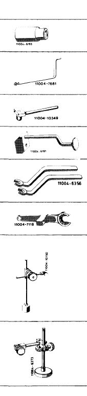 |
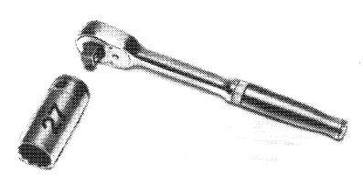
001 589 65 09 00
|
|||||||||||||||||||||||||||||||||||||||||||||||||||||||||
|
Socket 27 mm, 1/2″ square for rotating engine
|
|||||||||||||||||||||||||||||||||||||||||||||||||||||||||||
|
Measuring extension
|
123 589 09 63 00
|
||||||||||||||||||||||||||||||||||||||||||||||||||||||||||
|
Locating device for adjusting slide
|
116 589 19 21 00
|
||||||||||||||||||||||||||||||||||||||||||||||||||||||||||
|
Assembly mandrel for valve stem seals
|
617 589 00 43 00
|
||||||||||||||||||||||||||||||||||||||||||||||||||||||||||
|
Valve adjusting wrench 14 mm (2 each)
|
615 589 00 01 00
|
||||||||||||||||||||||||||||||||||||||||||||||||||||||||||
|
Holding wrench for valve spring retainer
|
615 589 00 03 00
|
||||||||||||||||||||||||||||||||||||||||||||||||||||||||||
|
Dial gauge holder
|
121 589 00 21 00
|
||||||||||||||||||||||||||||||||||||||||||||||||||||||||||
|
Magnetic dial gauge holder
|
116 589 12 21 00
|
||||||||||||||||||||||||||||||||||||||||||||||||||||||||||
|
|
|||||||||||||||||||||||||||||||||||||||||||||||||||||||||||
|
03.8-345/1 F 2
|
|||||||||||||||||||||||||||||||||||||||||||||||||||||||||||
|
|
|||||||||||||||||||||||||||||||||||||||||||||||||||||||||||
|
|
|||
|
Conventional tool
|
|||
|
|
|||
|
Dial gauge A 1 DIN 878
|
e.g. made by Mahr, D-7300 Esslingen order no. 810
|
||
|
|
|||
|
Note
|
 |
||
|
The pin in vibration damper should be accurately under TDC transmitter at crankshaft position 20° after TDC.
Check adjustment of TDC transmitter and make corrections, if required.
a) When renewing TDC transmitter adjusting slide.
b) When renewing crankshaft with balancing disc and vibration damper.
c) When completing basic engines.
With the cylinder head removed, the measuring pin of the dial gauge can be set directly on piston crown. For this purpose, place magnetic dial gauge holder on cylinder crankcase parting surface.
For adjusting TDC transmitter, proceed in this case according to item 7, 14 and 17—24.
|
|||
 |
|||
|
|
|||
|
Checking
|
|||
|
|
|||
|
1 Remove fan cover. For this purpose, disconnect upper coolant hose on radiator.
2 Remove fan.
3 Remove V-belt of power-steering pump and refrigerant compressor (13—340).
4 Remove double diaphragm or piston-vacuum pump.
|
|||
|
|
|||
|
03.8-345/2 F 2
|
|||
|
|
|||
|
|
|||
|
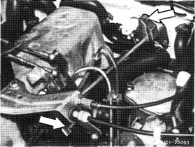
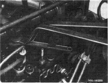
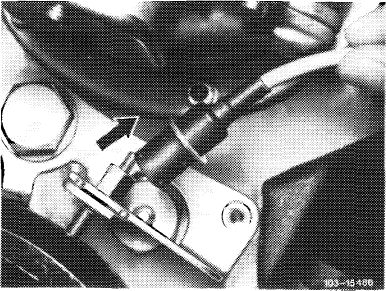
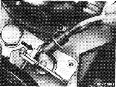
5 Disconnect regulating linkage to remove cylinder head cover. Pull out locking eye of longitudinal regulating shaft (arrow).
On models 116.120 and 123, pull longitudinal regulating shaft out of rubber mount in forward direction and remove in rearward direction.
On model 126.120, pull longitudinal regulating shaft out of guide lever in rearward direction and remove in forward direction.
|
 |
||
|
Model 116.120
|
|||
|
|
|||
|
Model 123
|
 |
||
|
|
|||
|
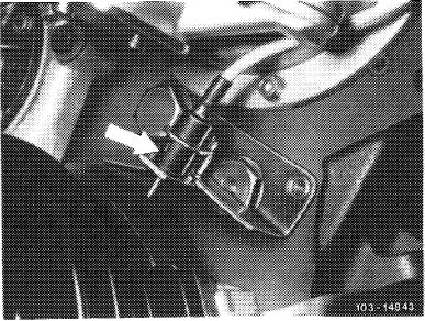
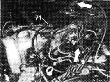
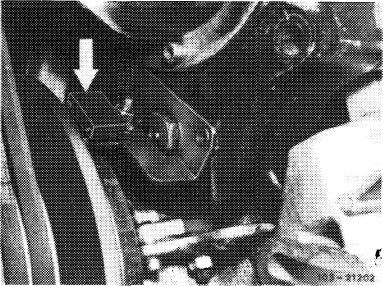
On models 123 with automatic transmission 722.303 (W4A 040) and 126.120, pull off central plug for vacuum lines (71) or vacuum lines. Disconnect bowden wire, compress black plastic clip (arrow) and pull bowden wire out of holder in rearward direction.
|
 |
||
|
Model 126.120
|
|||
|
|
|||
|
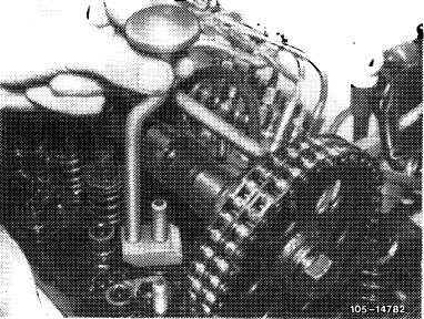
6 Remove front rocker arm group.
For this purpose, set camshaft in such a manner that
the rocker arms are not under load.
Attention!
Do not rotate engine on camshaft, but on crankshaft by means of tool combination.
|
 |
||
|
|
|||
|
03.8-345/3 F 2
|
|||
|
|
|||
|
|
|||
|
7 Set piston of 1st cylinder to TDC. Rotate crankshaft with tool combination.
|
 |
||
|
|
|||
|
110O-649S/1
|
|||
|
|
|||
|
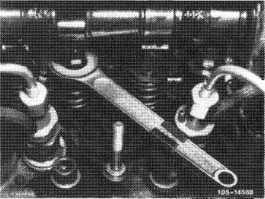
8 At intake valve of 1st cylinder, place holding wrench on hexagon of valve spring retainer.
|
 |
||
|
|
|||
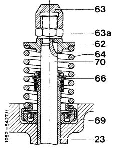
|
9 Unscrew cap nut (63) with valve adjusting wrench. For this purpose, apply counterhold to counternut (63a) by means of second valve adjusting wrench.
10 Unscrew counternut (63a).
|
 |
||
|
|
|||
 |
|||
|
|
|||
|
03.8-345/4 F 2
|
|||
|
|
|||
|
|
|||
|
11 Remove valve spring retainer and valve spring.
12 Push off valve stem seal by means of a screwdriver or pull off by means of pliers.
Attention!
Do not damage valve stem and valve guide.
13 Push valve on piston crown.
|
 |
||
|
|
|||
|
14 Reverse crankshaft for approx. 10 by means of tool combination.
15 Screw dial gauge holder with threaded sleeve to stud in cylinder head.
16 Insert dial gauge and screw measuring extension to dial gauge.
|
 |
||
|
|
|||
|
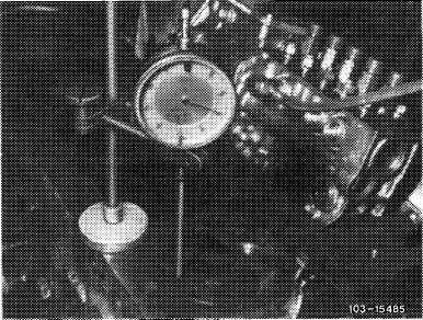
17 Place measuring arm on valve stem with 2 mm preload.
18 Slowly rotate crankshaft with tool combination in direction of rotation of engine until the large needle of the dial gauge stops (TDC position).
|
 |
||
|
|
|||
|
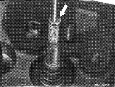
19 Unscrew TDC transmitter and pull out.
20 Loosen dial gauge and place measuring extension on valve stem at 5 mm preload. Rotate dial gauge scale until large needle points to zero.
21 Slowly rotate crankshaft with tool combination in direction of ratation of engine until dial gauge has moved back by 3.63 mm.
|
 |
||
|
|
|||
|
03.8-345/5 F 2
|
|||
|
|
|||
|
|
|||
|
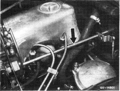
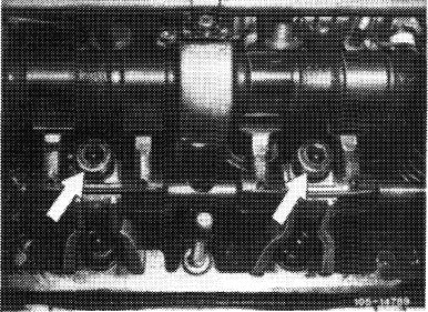
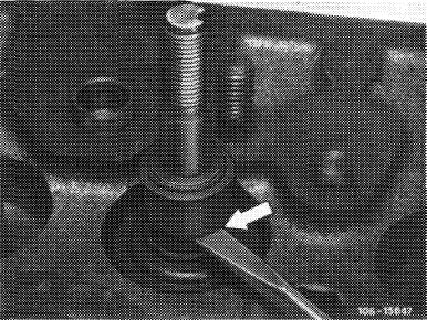
22 Place locating device without handle (arrow) into adjusting slide.
Pin in balancing disc should enter groove of locating device.
If pin is not engaging, correct position of adjusting slide.
|
 |
||
|
|
|||
|
Correcting
|
 |
||
|
23 Loosen adjusting slide and displace until pin in balancing disc enters groove of locating device.
24 Screw down adjusting slide and remove locating device.
|
|||
|
|
|||
|
25 Insert TDC transmitter and tighten.
26 Remove dial gauge and unscrew dial gauge holder.
27 Lubricate new valve stem seal and mount with assembly mandrel. For this purpose, place an assembly sleeve on valve stem.
28 Install valve spring and rocker arm group.
|
 |
||
|
|
|||
|
29 Check valve clearance (05-210).
30 Mount cylinder head cover.
31 Install double diaphragm or piston-vacuum pump with new gasket.
32 Mount V-belt of powersteering pump and refrigerant compressor and tension (13-340).
33 Attach fan and fan cover.
|
|||
|
|
|||
|
03.8-345/6 F 2
|
|||
|
|
|||