Removal and installation of complete oil pan
|
|
||||||||||||||||||||||||||||
|
01—310 Removal and installation of complete oil pan
|
||||||||||||||||||||||||||||
|
|
||||||||||||||||||||||||||||
|
||||||||||||||||||||||||||||
|
|
||||||||||||||||||||||||||||
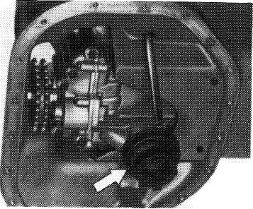
|
Tightening torques
|
Nm
|
|||||||||||||||||||||||||||
|
|
||||||||||||||||||||||||||||
|
Oil drain plug to oil pan
|
40
|
|||||||||||||||||||||||||||
|
|
||||||||||||||||||||||||||||
|
Oil pan upper half to cylinder crankcase
|
||||||||||||||||||||||||||||
|
|
||||||||||||||||||||||||||||
|
10
|
||||||||||||||||||||||||||||
|
|
||||||||||||||||||||||||||||
|
Oil pan lower half to upper half
|
||||||||||||||||||||||||||||
|
|
||||||||||||||||||||||||||||
|
Engine carrier to engine mount front
|
70
|
|||||||||||||||||||||||||||
|
|
||||||||||||||||||||||||||||
|
Special tools
|
||||||||||||||||||||||||||||
|
|
||||||||||||||||||||||||||||
|
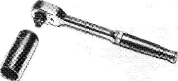
Torque wrench with plug-in ratchet, 1/2″ square, 25-130 Nm
Torque wrench with plug-in ratchet, 1/2″ square, 40-200 Nm
|
 |
001 589 66 21 00
|
||||||||||||||||||||||||||
|
001 589 67 21 00
|
||||||||||||||||||||||||||||
|
|
||||||||||||||||||||||||||||
|
Screwdriver (Allen wrench) with tommy handle for hex. socket screws 5 mm, 300 mm long
|
 |
116 589 02 07 00
|
||||||||||||||||||||||||||
|
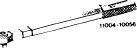
Knock-out mandrel
Socket 27 mm, 1/2″ square for rotating engine
Knocking-in tool for oil dipstick guide tube
|
110 589 02 15 00 001 589 65 09 00
117 589 00 31 00
|
|||||||||||||||||||||||||||
|
|
||||||||||||||||||||||||||||
|
Conventional tool
|
||||||||||||||||||||||||||||
|
|
||||||||||||||||||||||||||||
|
Engine hoist (Motordirigent) size 1.5
|
e.g. made by Backer, D-5630 Remscheid order no. 3178
|
|||||||||||||||||||||||||||
|
|
||||||||||||||||||||||||||||
|
01.8-310/1 F2
|
||||||||||||||||||||||||||||
|
|
||||||||||||||||||||||||||||
|
|
|||
|
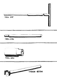
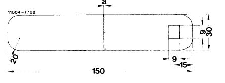
Self-made tool
|
|||
|
|
|||
|
Gauge for cutting off rear radial sealing ring
|
 |
||
|
Dimension a = 1.0 mm
|
|||
|
|
|||
|
Note
|
|||
|
|
|||
|
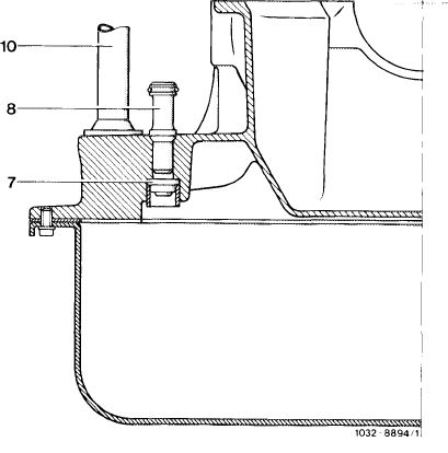
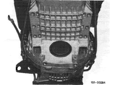
There are four oil pan upper half versions.
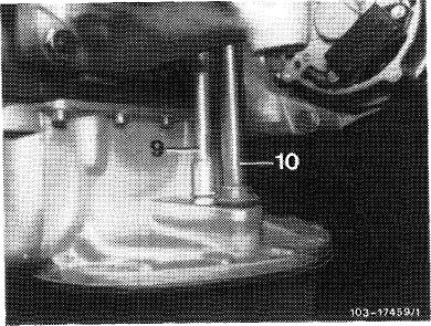
a) Oil pan upper half with a connection for oil return line (10) from exhaust gas turbocharger.
Installed on engines 617.950 (model 116.120) without EGR <@) and 617.952 (model 123) with automatic transmission 722.120 (W4B025).
|
|||
|
|
|||
|
b) Oil pan upper half with two connections for oil return line (10) from exhaust gas turbocharger and from cyclonic oil separator (8) in air cleaner.
Installed in engine 617.950 (model 116.120) with EGR (usa).
|
 |
||
|
7 Check valve
8 Oil return line from cyclonic oil separator
10 Oil return line from exhaust gas turbocharger
|
|||
|
|
|||
|
c) Oil pan upper half with integrated supporting shell and a connection for oil return line (10) from exhaust gas turbocharger.
Installed on engine 617.952 (model 123) with automat transmission 722.303 (W4A040).
|
 |
||
|
|
|||
|
01.8-310/2 F2
|
|||
|
|
|||
|
|
|||
|
d) Oil pan upper half with integrated supporting shell and two connections for oil return line (10) from exhaust gas turbocharger and from cyclonic oil separator (8) in air cleaner.
Installed on engine 617.951 (model 126.120) and 617.952 (model 123) with automatic transmission 722.303 (W4A040).
|
|||
|
|
|||
|
Spare part oil pan upper halves for engines with EGR (usa)are provided with check valve (7) and oil return line (8).
They can not be installed on engines without EGR.
On model 126.120 with engine, remove and install (01-030).
|
|||
|
|
|||
|
Removal
|
|||
|
|
|||
|
1 Drain engine oil.
|
|||
|
|
|||
|
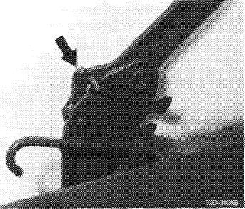
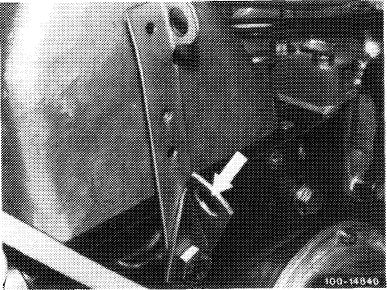
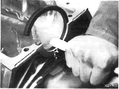
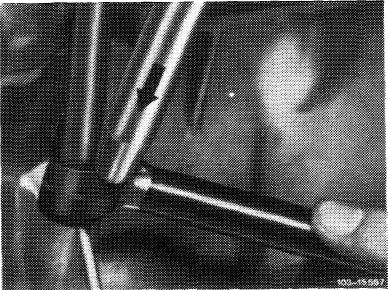
2 On model 116.120, remove engine hood.
On model 123, move engine hood into 90 ° position and engage detent lever (arrow).
|
 |
||
|
|
|||
|
01.8-310/3 F2
|
|||
|
|
|||
|
|
|||
|
3 Remove intermediate member on air cleaner (arrow).
4 Unscrew fan cover and place over fan; loosen radiator.
|
 |
||
|
|
|||
|
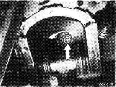
5 Remove longitudinal regulating shaft. For this purpose, pull out locking eye (arrow).
|
 |
||
|
Model 116.120
|
|||
|
|
|||
|
On models 116.120 and 123, pull longitudinal regulating shaft out of rubber mount in forward direction and remove in rearward direction.
|
 |
||
|
Model 123
|
|||
|
|
|||
|
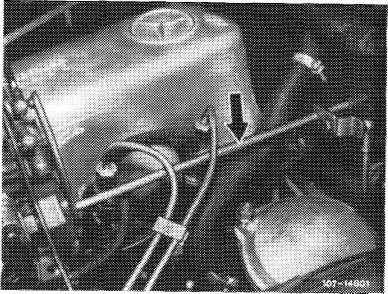
6 Unscrew holding clamp of oil dipstick guide tube on power steering pump mounting bracket.
|
 |
||
|
|
|||
|
01.8-310/4 F2
|
|||
|
|
|||
|
|
|||
|
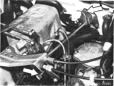
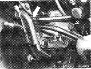
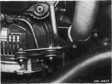
7 Slacken V-belt of refrigerant compressor and remove.
Unscrew refrigerant compressor with carrier. For this purpose, unscrew screws (1—4) and loosen clamp (arrow) of air-oil cooler lines.
|
 |
||
|
|
|||
|
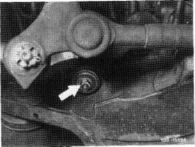
8 Unscrew both engine shock-absorbers on frame cross member or console for lower control arm.
|
 |
||
|
|
|||
|
9 Loosen exhaust lateral support on transmission.
|
 |
||
|
|
|||
|
10 Unscrew fastening screws of engine carrier on engine mount from below.
11 Unscrew oil cooler lines for automatic transmission, on transmission, on intermediate flange and on oil pan upper half.
|
 |
||
|
|
|||
|
01.8-310/5 F2
|
|||
|
|
|||
|
|
|||
|
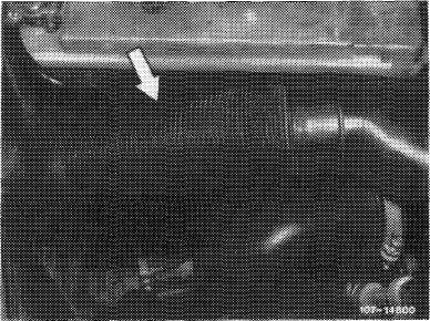
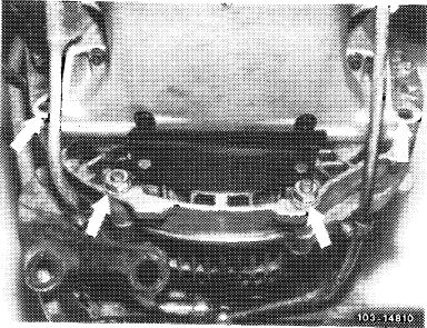
12 Unscrew the 4 lower screws on intermediate flange (arrows).
13 Unscrew cover plate on intermediate flange.
14 Unscrew oil pan lower half and remove.
|
 |
||
|
|
|||
|
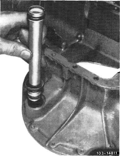
15 Knock-out oil dipstick guide tube as far as possible by means of knocking-out mandrel 9 mm dia. for valve guides.
Attention!
The oil dipstick guide tube cannot yet be pulled out.
|
 |
||
|
|
|||
|
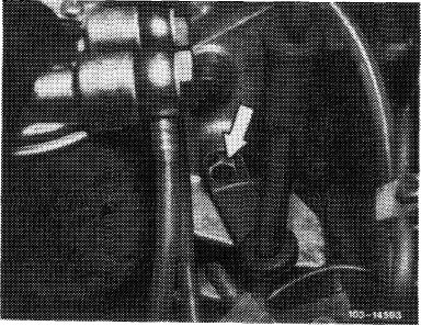
16 Pull off adaptor with strainer on oil pump (arrow).
17 Unscrew oil pan upper half.
|
J03-MS03/1
|
||
|
|
|||
|
01.8-310/6 F2
|
|||
|
|
|||
|
|
|||
|
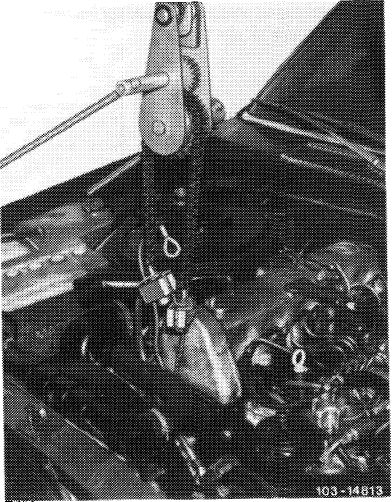
18 Attach rope of engine hoist (Motordirigent) to suspension eye at front on cylinder head (arrow).
|
 |
||
|
|
|||
|
19 Lift engine as far as possible by means of engine hoist and a crane. For this purpose, on model 123, open rear clamp on air cleaner so that it will not abut against battery while lifting.
|
 |
||
|
20 Pull out oil dipstick guide tube.
21 Pull oil pan in downward direction and remove in forward direction.
|
|||
|
|
|||
|
To remove oil pan, turn crankshaft with tool combination until oil pan upper half can be pulled past connecting rod or crankshaft webs.
22 Thoroughly clean parting surface on cylinder crankcase, on oil pan upper and lower half.
|
 |
||
|
|
|||
|
R 100/6498
|
|||
|
|
|||
|
01.8-310/7 F2
|
|||
|
|
|||
|
|
|||
|
Installation
|
 |
||
|
Note: If a new oil pan upper half is installed, insert oil return pipe and contoured gasket first.
Renew damaged or porous contour gaskets and O-rings.
|
|||
|
When removing oil return pipe, push out contoured sealing ring from oil pan first.
|
|||
|
|
|||
|
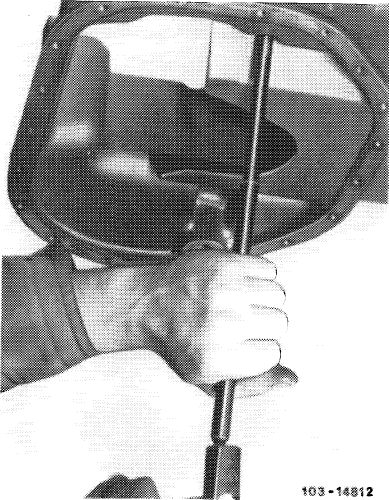
23 Renew rear radial sealing ring in oil pan according to condition.
Insert new radial sealing ring into groove and work in with a lubricated hammer handle.
|
 |
||
|
|
|||
|
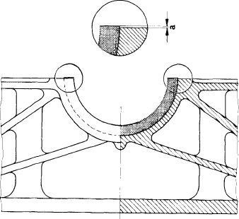
24 To obtain an overlap, cut off radial sealing ring 1 mm above parting surface, using self-made gauge.
25 Provide radial sealing ring with engine oil.
|
|||
|
|
|||
|
Dimension a = 1.0 mm
|
|||
|
|
|||
|
Z033-4001/I
 |
|||
|
|
|||
|
01.8-310/8 F2
|
|||
|
|
|||
|
|
|||
|
26 Coat parting surface of oil pan top uniformly with sealing compound, part no. 001 989 46 20. Use this type of sealing compound only.
27 Position oil pan upper half, while inserting oil dipstick guide pipe, oil return pipe from exhaust gas turbocharger and from cyclonic oil separator (on engines with EGR only).
|
 |
||
|
9 Oil return line from cyclonic oil separator 10 Oil return line from exhaust gas turbocharger
|
|||
|
|
|||
|
28 Screw down oil pan upper half.
|
|||
|
|
|||
|
29 Knock-in oil dipstick guide tube up to flange by means of knocking-in tool.
30 Lower engine. Pay attention to installation position of shielding plates and guide engine shock-absorbers into bores on frame cross member.
31 Insert adaptor with strainer at oil pump.
|
 |
||
|
|
|||
|
32 Screw-on oil pan lower half with new gasket.
|
|||
|
|
|||
|
33 For further installation proceed vice versa.
|
|||
|
|
|||
|
34 Add engine oil.
|
|||
|
|
|||
|
35 Run engine and add gear oil.
|
|||
|
|
|||
|
36 Run engine warm and check for leaks.
|
|||
|
|
|||
|
01.8-310/9 F2
|
|||
|
|
|||
|
|
|||
|
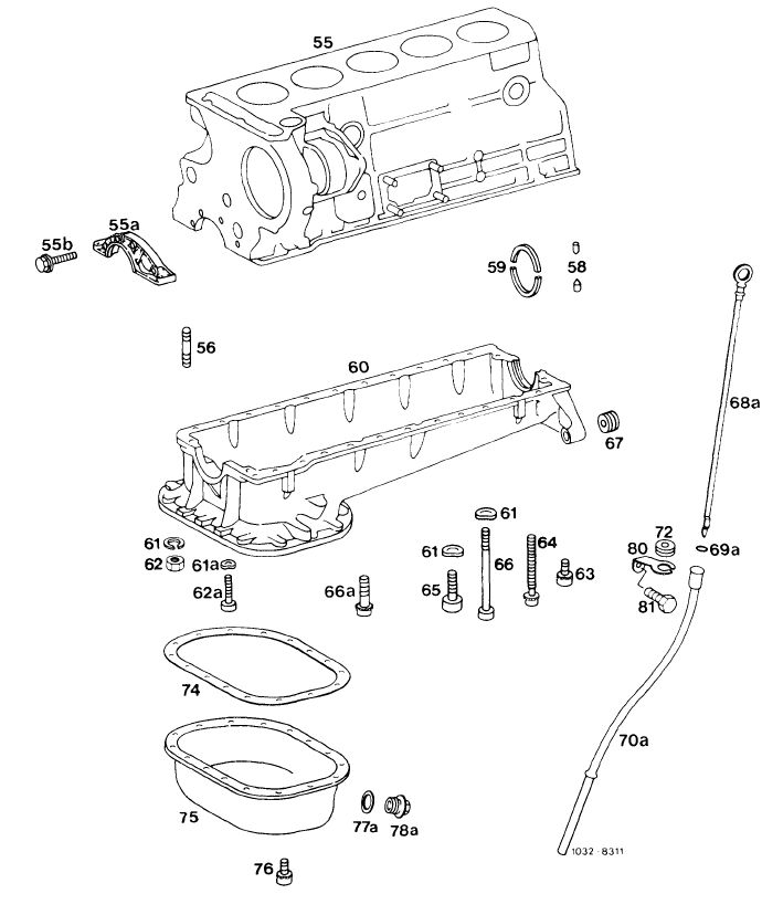
Cylinder crankcase and oil pan
|
|||
|
|
|||
 |
|||
|
|
|||
|
55 Cylinder crankcase 65 55a Cover
55b 4 combination screws M 6 x 25 66
56 2 screws M 8 x 25 66a
58 Locking pin 67
59 Crankshaft radial sealing ring 68a
60 Oil pan top 69a
61 4 spring washers B 8 70a 61a 2 spring washers B 6 72
62 2 nuts M 8 74 62a 2 screws M 6×20 75
63 16 combination screws M 6×15 76 (engine 617.950/952) 77a 14 combination screws M 6×15 78a (engine 617.951) 80
64 2 combination screws M 6×60 81 (engine 617.950/952)
8 combination screws M 6×60 (engine 617.951)
|
4 combination screws M 6×30
(engine 617.950/952
2 screws M 8×95
2 screws M 8×20
2 threaded inserts 10/14×20 (engine 617.950/952)
Oil dipstick
O-ring
Oil dipstick guide tube
Rubber grommet
Gasket
Oil pan lower half
Combination screw M 6×15 (19 each)
Sealing ring A 12×17
Oil drain plug M 12
Holder for oil dipstick guide tube
Screw M 8×12
|
||
|
|
|||
|
01.8-310/10 F2
|
|||
|
|
|||