Installation and centering of intermediate flange
|
|
||||
|
01—220 Installation and centering of intermediate flange
|
||||
|
|
||||
|
Data
|
||||
|
|
||||
|
Vertical runout of intermediate flange
|
max. 0.10
|
|||
|
|
||||
|
Tightening torques
|
Nm
|
|||
|
|
||||
|
Fastening screws for intermediate flange
|
50
|
|||
|
|
||||
|
initial torque
|
40
|
|||
|
|
||||
|
Necked-down screw for driven plate and flywheel
|
||||
|
|
||||
|
angle of rotation torque 90—100°
|
||||
|
|
||||
|
Special tools
|
||||
|
|
||||
|
Dial gauge holder (2 each required)
|
 |
363 589 02 21 00
|
||
|
|
||||
|
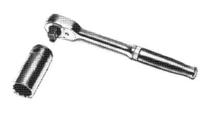
Socket 27 mm, 1/2″ square for rotating engine
|
 |
001 589 65 09 00
|
||
|
|
||||
|
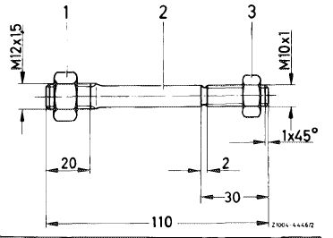
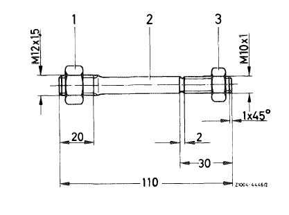
Self-made tool
|
||||
|
|
||||
|
Threaded bolt
|
 |
|||
|
|
||||
|
01.8-220/1 F2
|
||||
|
|
||||
|
|
||||
|
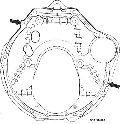
The intermediate flange is provided with two additional bores for centering the fitted pins of automatic transmission 722.303 (W 4 A 040).
This intermediate flange is also installed on engines with automatic transmission 722.120 (W 4 B 025). Part no. 615 011 02 45.
|
 |
|||
|
Start of series: February 1980
|
||||
|
Model
|
Engine end no. _, Engine Chassis end no.
|
|||
|
|
||||
|
116.120 617.950 022432 022082
123 617.952 start of series
126.120 617.951 start of series
|
||||
|
|
||||
|
Installation and centering
|
 |
|||
|
1 Insert intermediate flange into fitted pins on cylinder crankcase.
2 Slightly tighten the four fastening screws.
3 Screw threaded bolt (self-made) into crankshaft and counterlock with hex. nut.
|
||||
|
|
||||
|
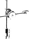
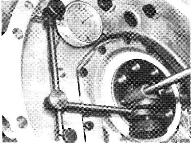
4 Attach dial gauge holder with dial gauge to threaded bolt.
5 Position feeler pin against OD of round center.
|
 |
|||
|
Shown on engine 116
|
||||
|
|
||||
|
01.8-220/2 F2
|
||||
|
|
||||
|
|
|||
|
6 Turn crankshaft with tool combination and measure vertical runout. Vertical runout should not exceed max. 0.10 mm.
Note: When turning crankshaft, make sure that feeler pin of dial gauge is not getting stuck.
7 Correct vertical runout by means of light blows against intermediate flange.
|
 |
||
|
|
|||
|
R10Q/6498
|
|||
|
|
|||
|
8 Tighten fastening screws.
Note: If the vertical runout exceeds 0.10 mm, remove intermediate flange.
9 Drill both fitted bores in intermediate flange to 12.1 mm.
10 Repeat item 1—8.
|
|||
|
|
|||
|
01.8-220/3 F2
|
|||
|
|
|||