Removal and installation of camshaft
|
|
|||||||||||||||||||||||||||||||||||||||||||||||||||||||||||||||||||||||||||||||||
|
05—220 Removal and installation of camshaft
|
|||||||||||||||||||||||||||||||||||||||||||||||||||||||||||||||||||||||||||||||||
|
|
|||||||||||||||||||||||||||||||||||||||||||||||||||||||||||||||||||||||||||||||||
|
Timing at 2 mm valve lift
|
|||||||||||||||||||||||||||||||||||||||||||||||||||||||||||||||||||||||||||||||||
|
|
|||||||||||||||||||||||||||||||||||||||||||||||||||||||||||||||||||||||||||||||||
|
|||||||||||||||||||||||||||||||||||||||||||||||||||||||||||||||||||||||||||||||||
|
|
|||||||||||||||||||||||||||||||||||||||||||||||||||||||||||||||||||||||||||||||||
|
1) Camshaft code number is punched into rear end of camshaft.
2) ({J^J\ up to model year 1979. 3)—–model year 1980.
4) Camshaft made of chilled cast iron.
|
|||||||||||||||||||||||||||||||||||||||||||||||||||||||||||||||||||||||||||||||||
|
|
|||||||||||||||||||||||||||||||||||||||||||||||||||||||||||||||||||||||||||||||||
|
|||||||||||||||||||||||||||||||||||||||||||||||||||||||||||||||||||||||||||||||||
|
|
|||||||||||||||||||||||||||||||||||||||||||||||||||||||||||||||||||||||||||||||||
|
Permissible runout of center bearing journal and camshaft sprocket seat when mounting camshaft in outer bearing journals
|
Camshaft code number
|
00
|
05,08
|
||||||||||||||||||||||||||||||||||||||||||||||||||||||||||||||||||||||||||||||
|
Camshaft sprocket seat 2nd bearing point 3rd bearing point
|
|
||||||||||||||||||||||||||||||||||||||||||||||||||||||||||||||||||||||||||||||||
|
|
|||||||||||||||||||||||||||||||||||||||||||||||||||||||||||||||||||||||||||||||||
|
|||||||||||||||||||||||||||||||||||||||||||||||||||||||||||||||||||||||||||||||||
|
|
|||||||||||||||||||||||||||||||||||||||||||||||||||||||||||||||||||||||||||||||||
|
Camshaft bearing bolts (double hex. socket cylinder head bolts)
|
|
||||||||||||||||||||||||||||||||||||||||||||||||||||||||||||||||||||||||||||||||
|
|
|||||||||||||||||||||||||||||||||||||||||||||||||||||||||||||||||||||||||||||||||
|
05.8-220/1 F 2
|
|||||||||||||||||||||||||||||||||||||||||||||||||||||||||||||||||||||||||||||||||
|
|
|||||||||||||||||||||||||||||||||||||||||||||||||||||||||||||||||||||||||||||||||
|
|
|||||
|
Nuts M 8 for camshaft bearings Necked-down screw for camshaft sprocket Rocker arm bearing brackets to cylinder head
Special tools
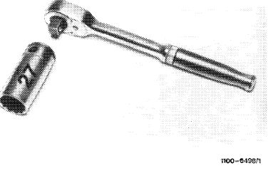
Socket 27 mm, 1/2″ square, for rotating engine
|
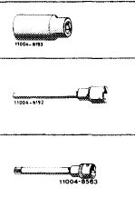 |
25 80 40
001 589 65 09 00
|
|||
|
Screwdriver socket 10 mm, 1/2″ square, 140 mm long for hex. socket cylinder head bolts
|
000 589 05 07 00
|
||||
|
Screwdriver socket 1/2″ square, 140 mm long for double hex. socket cylinder head bolts
|
617 589 00 10 00
|
||||
|
|
|||||
|
Valve adjusting wrench 14 mm (2 each)
|
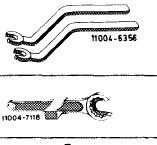 |
615 589 00 01 00
|
|||
|
Holding wrench for valve spring retainer
|
615 589 00 03 00
|
||||
|
Impact puller for bearing bolt (basic unit)
|
 |
116 589 20 33 00
|
|||
|
|
|||||
|
Threaded bolt for impact puller M 6, 50 mm long
|
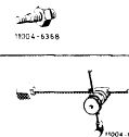 |
116 589 01 34 00
|
|||
|
Dial gage holder
|
363 589 02 21 00
|
||||
|
|
|||||
|
Contact handle for rotating engine (component of compression pressure recorder 001 589 46 21 00)
|
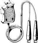 |
001 589 46 21 08
|
|||
|
11004-8487
|
|||||
|
|
|||||
|
Conventional tool
|
|||||
|
|
|||||
|
Dial gage A 1 DIN 878
|
e.g. made by Mahr, D-7300 Esslingen Order No. 810
|
||||
|
|
|||||
|
05.8-220/2 F 2
|
|||||
|
|
|||||
|
|
||||
|
Note
When installing a new camshaft, also renew rocker arms on principle.
Of rocker arms with carbide facing, replace damaged rocker arms only.
|
||||
|
|
||||
|
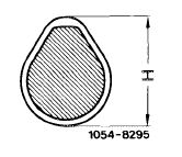
The larger cylinder charge required for engine 617.950 (usa) model year 1980 with increased output and on engines 617.951/952 has been obtained by increasing the valve lift.
For this purpose, the intake and exhaust cams on camshaft have been modified with regard to height (H) and shape.
|
 |
|||
|
|
||||
|
Valve lift on engine 617.950 <@) model year 1980 with increased output and on engines 617.951/952.
|
||||
|
|
||||
|
Intake Exhaust
|
10.0 mm 10.4 mm
|
|||
|
|
||||
|
Valve lift on engine 617.950(@)without increased output up to model year 1979.
Intake and exhaust 8.5 mm
|
||||
|
|
||||
|
Since the above measures result in higher loads on camshafts, a different materials pairing between camshaft and rocker arm has been required.
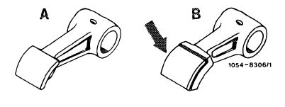
Camshafts of engine 617.950<@)model year 1980 with increased output and of engines 617.951/952 (code number 05) are made of chilled cast iron, and the sliding surface of the respective rocker arms is provided with a brazed-on carbide facing (B, arrow).
|
 |
|||
|
A Rocker arm inductance-hardened and hard-chromed B Rocker arm with carbide facing
|
||||
|
|
||||
|
05.8-220/3 F 2
|
||||
|
|
||||
|
|
||||||||||||||||||||||||||||||||||||||
|
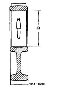
Because of the larger valve lift (higher cams) and in order to permit installation of camshaft, the bearing diameter (D) at camshaft bearings 2, 3 and 4 had to be increased by 2.5 mm. Accordingly, the diameter of bearing journals 2, 3 and 4 of camshaft has also been increased by 2.5 mm.
|
 |
|||||||||||||||||||||||||||||||||||||
|
Camshaft bearings 2, 3 and 4
Engines without increased output D = 46.5 mm Engines with increased output D = 49.0 mm
|
||||||||||||||||||||||||||||||||||||||
|
|
||||||||||||||||||||||||||||||||||||||
|
In addition, camshaft bearings 2, 3 and 4 have been reinforced (B).
On the other hand, the diameter of the first camshaft bearing and the first camshaft bearing journal has remained the same.
Since the wear characteristics of camshafts made of chilled cast iron are better than those made of malleable cast iron, the malleable cast iron camshaft (code number 00) for engine 617.950(ysA)for model year 1979 without increased output has been replaced by the chilled cast iron camshaft (code number 08) (refer to table).
This camshaft also includes the rocker arms with carbide facing.
|
 |
|||||||||||||||||||||||||||||||||||||
|
|
||||||||||||||||||||||||||||||||||||||
|
||||||||||||||||||||||||||||||||||||||
|
|
||||||||||||||||||||||||||||||||||||||
|
The chilled cast iron camshafts (code number 05 and 08) may be installed only together with the carbide-faced rocker arms.
Rocker arms with carbide facing may not be installed together with malleable cast-iron camshaft (code number 00).
It is also not permitted to install engine 617.950 (@) model year 1980 with increased output and engines 617.951/952 on engine 617.950<@)up to model year 1979.
|
||||||||||||||||||||||||||||||||||||||
|
|
||||||||||||||||||||||||||||||||||||||
|
05.8-220/4 F 2
|
||||||||||||||||||||||||||||||||||||||
|
|
||||||||||||||||||||||||||||||||||||||
|
|
|||
|
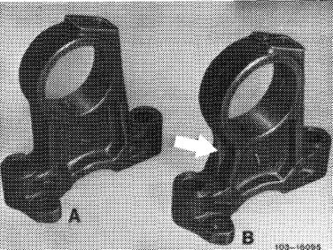
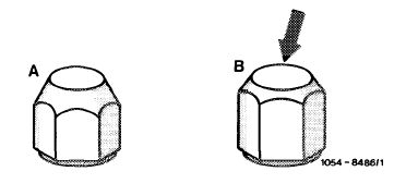
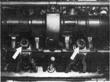
Simultaneously with the changeover to chilled cast iron camshaft and rocker arms with carbide facing, the cap nuts in upper range were reinforced and hard-chromed (B).
They may be installed on all rocker arm versions.
On the other hand, the non-chrome-plated cap nut may not be used for rocker arm with carbide facing.
|
 |
||
|
A Cap nut without chrome plating B Cap nut with chrome plating
|
|||
|
|
|||
|
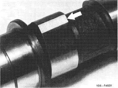
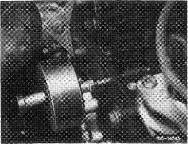
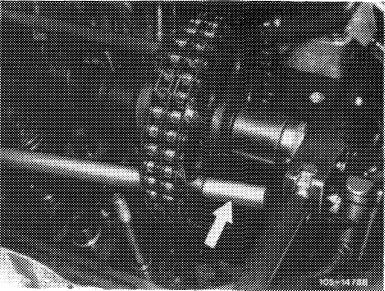
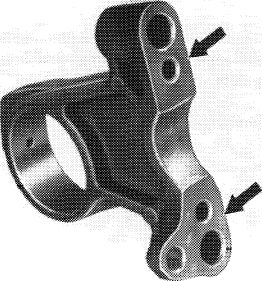
Chilled cast iron camshafts are sensitive to fracture and should not be knocked against, struck or thrown.
Camshafts on which flats are showing up on cams (arrow) should be replaced.
The timing should be checked on engines after a long period of operation (extensive elongation of chain) (05-215).
|
 |
||
|
Worn out camshaft bearing journals may be reground. The required camshaft bearings are available in two repair stages (05-225).
|
|||
|
|
|||
|
Removal
|
 |
||
|
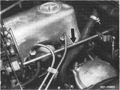
1 Disconnect regulating linkage to remove cylinder head cover. Pull out locking eye of longitudinal regulating shaft (arrow).
|
|||
|
Model 116.120
|
|||
|
|
|||
|
On models 116.120 and 123, pull longitudinal regulating shaft out of rubber mount in forward direction and remove in rearward direction.
On model 126.120, pull longitudinal regulating shaft out of guide lever in rearward direction and remove in forward direction.
|
 |
||
|
Model 123
|
|||
|
|
|||
|
05.8-220/5 F 2
|
|||
|
|
|||
|
|
|||
|
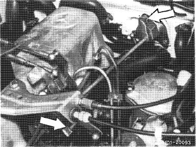
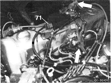
On models 123 with automatic transmission 722.303 (W 4 A 040) and 126.120, pull off central plug for vacuum lines (71) or vacuum lines. Disconnect Bowden wire, compress black plastic clip (arrow) and pull Bowden wire out of holder in rearward direction.
|
 |
||
|
Model 126.120
|
|||
|
|
|||
|
2 Remove rocker arms together with rocker arm brackets (05-235).
|
 |
||
|
|
|||
|
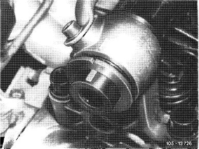
3 Remove slide rail in cylinder head. Pull out bearing bolt by means of impact puller.
|
 |
||
|
|
|||
 |
|||
|
|
|||
|
05.8-220/6 F 2
|
|||
|
|
|||
|
|
|||
|
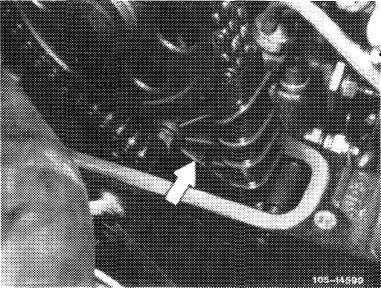
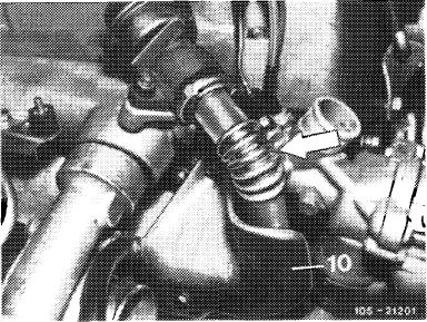
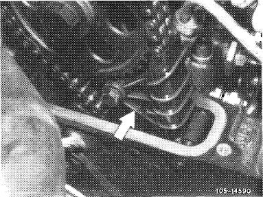
4 On engines with EGR (@), remove pipe line between EGR valve and exhaust manifold (arrow). Unscrew shielding plate (10) for this purpose.
|
 |
||
|
|
|||
|
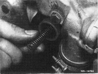
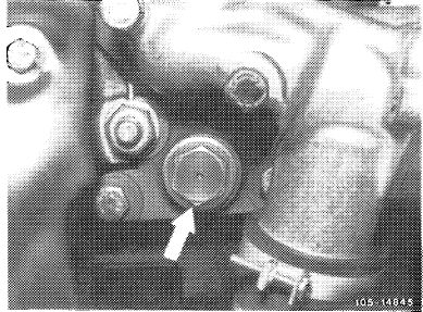
5 Unscrew closing plug of chain tensioner and remove compression spring (05—310).
|
 |
||
|
|
|||
|
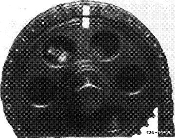
6 Set crankshaft to ignition TDC.
Rotate crankshaft with tool combination for this purpose.
|
 |
||
|
|
|||
|
7 Mark camshaft sprocket and timing chain in relation to each other.
|
 |
||
|
|
|||
|
05.8-220/7 F 2
|
|||
|
|
|||
|
|
|||
|
8 Remove camshaft sprocket.
To loosen necked-down screw, apply counterhold to camshaft sprocket by means of a screwdriver or a steel bolt.
|
 |
||
|
|
|||
|
9 Remove compensating washer.
|
 |
||
|
|
|||
|
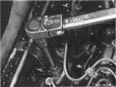
10 Unscrew camshaft bearing screws by means of screwdriver socket (10 mm).
Unscrew nuts M 8.
|
 |
||
|
|
|||
|
11 Remove camshaft together with camshaft bearings and oil pipe.
Pay attention to dowel pins.
Loosen stuck camshaft bearings by means of light blows with a plastic hammer.
12 Pull camshaft out of camshaft bearings in rearward direction.
|
|||
|
|
|||
|
05.8-220/8 F 2
|
|||
|
|
|||
|
|
||||
|
Installation
|
||||
|
|
||||
|
13 Provide camshaft bearings, camshaft bearing journals and cams with engine oil.
14 Slip camshaft from the rear into camshaft bearings.
15 Mount camshaft with camshaft bearings and oil pipe.
Pay attention to dowel pins.
|
||||
|
|
||||
|
16 Tighten camshaft bearing bolts (cylinder head bolts) from inside out as specified (refer to table).
On engines with hex. socket cylinder head bolts, slightly loosen the remaining 14 cylinder head bolts also from inside out individually and tighten to 100 Nm.
Tighten M 8 nuts to 25 Nm.
|
 |
|||
|
|
||||
|
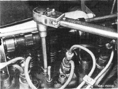
17 Rotate camshaft manually to check for easy operation.
If camshaft is hard to rotate, proceed as follows:
Loosen camshaft bearings individually. Then rotate camshaft each time.
|
||||
|
|
||||
|
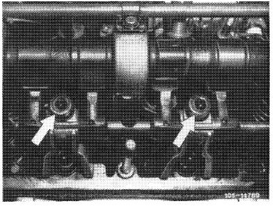
Repeat until the binding bearing point is found. Depending on sag of camshaft, touch up pertinent camshaft bearing at base (arrows) on a surface plate.
18 Slip compensating washer on journal for camshaft sprocket.
|
 |
105-15583
|
||
|
|
||||
|
05.8-220/9 F 2
|
||||
|
|
||||
|
|
|||
|
19 Mount camshaft sprocket. Pay attention to color marks.
Tighten necked-down screw to 80 Nm. For this purpose, apply counterhold to camshaft sprocket by means of a screwdriver or steel bolt.
20 Install slide rail.
|
 |
||
|
|
|||
|
21 Place compression spring into chain tensioner and tighten closing plug to 90 Nm.
|
 |
||
|
|
|||
|
22 Install rocker arms together with rocker arm bearing brackets (05—235).
|
 |
||
|
|
|||
|
23 Adjust valve clearance (05-210).
24 On engines with EGR (@), install pipe line between EGR valve and exhaust manifold. Screw on shielding plate.
25 Mount cylinder head cover.
|
 |
||
|
|
|||
|
05.8-220/10 F2
|
|||
|
|
|||
|
|
|||||||||||||||||||||||||||||||||||||||||||||||||||||||||||
|
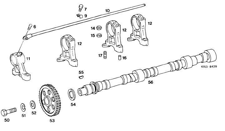
Camshaft and camshaft bearings
|
|||||||||||||||||||||||||||||||||||||||||||||||||||||||||||
|
|
|||||||||||||||||||||||||||||||||||||||||||||||||||||||||||
 |
|||||||||||||||||||||||||||||||||||||||||||||||||||||||||||
|
|
|||||||||||||||||||||||||||||||||||||||||||||||||||||||||||
|
6 Combination screw M 6 x 12
7 3 combination screws M 5 x 10 9 3 fastening clamps
10 Oil pipe
11 Camshaft bearing crank end
12 Camshaft bearing
|
|
||||||||||||||||||||||||||||||||||||||||||||||||||||||||||
|
|
|||||||||||||||||||||||||||||||||||||||||||||||||||||||||||
|
05.8-220/11 F2
|
|||||||||||||||||||||||||||||||||||||||||||||||||||||||||||
|
|
|||||||||||||||||||||||||||||||||||||||||||||||||||||||||||