Inspection and adjustment of camshaft timing
|
|
|||||||||||||||||||||||||||||||||||||||||||||||||||||||||||||||||||||||||||||||||
|
05—215 Inspection and adjustment of camshaft timing
|
|||||||||||||||||||||||||||||||||||||||||||||||||||||||||||||||||||||||||||||||||
|
|
|||||||||||||||||||||||||||||||||||||||||||||||||||||||||||||||||||||||||||||||||
|
Timing at 2 mm valve lift
|
|||||||||||||||||||||||||||||||||||||||||||||||||||||||||||||||||||||||||||||||||
|
|
|||||||||||||||||||||||||||||||||||||||||||||||||||||||||||||||||||||||||||||||||
|
|||||||||||||||||||||||||||||||||||||||||||||||||||||||||||||||||||||||||||||||||
|
|
|||||||||||||||||||||||||||||||||||||||||||||||||||||||||||||||||||||||||||||||||
|
M Camshaft code number is punched into rear end of camshaft.
2) ^r\ up to model year 1979.
3) ^3″ model year 1980.
4) Camshaft made of chilled cast iron.
|
|||||||||||||||||||||||||||||||||||||||||||||||||||||||||||||||||||||||||||||||||
|
|
|||||||||||||||||||||||||||||||||||||||||||||||||||||||||||||||||||||||||||||||||
|
Valve clearance
|
with engine cold (approx. 20 °C)
|
with engine warm (60 °C ± 15 °C)
|
|||||||||||||||||||||||||||||||||||||||||||||||||||||||||||||||||||||||||||||||
|
|
|||||||||||||||||||||||||||||||||||||||||||||||||||||||||||||||||||||||||||||||||
|
|||||||||||||||||||||||||||||||||||||||||||||||||||||||||||||||||||||||||||||||||
|
|
|||||||||||||||||||||||||||||||||||||||||||||||||||||||||||||||||||||||||||||||||
|
Valve adjusting wrench 14 mm (2 each)
|
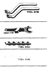 |
615 589 00 01 00
|
|||||||||||||||||||||||||||||||||||||||||||||||||||||||||||||||||||||||||||||||
|
Holding wrench for valve spring retainer
|
615 589 00 03 00
|
||||||||||||||||||||||||||||||||||||||||||||||||||||||||||||||||||||||||||||||||
|
Slip gage holder, red
|
617 589 00 40 00
|
||||||||||||||||||||||||||||||||||||||||||||||||||||||||||||||||||||||||||||||||
|
Slip gage blades
|
0.10 mm thick 0.15 mm thick
|
617 589 00 23 00 617 589 01 23 00
|
|||||||||||||||||||||||||||||||||||||||||||||||||||||||||||||||||||||||||||||||
|
|
|||||||||||||||||||||||||||||||||||||||||||||||||||||||||||||||||||||||||||||||||
|
05.8-215/1 F2
|
|||||||||||||||||||||||||||||||||||||||||||||||||||||||||||||||||||||||||||||||||
|
|
|||||||||||||||||||||||||||||||||||||||||||||||||||||||||||||||||||||||||||||||||
|
|
||||||
|
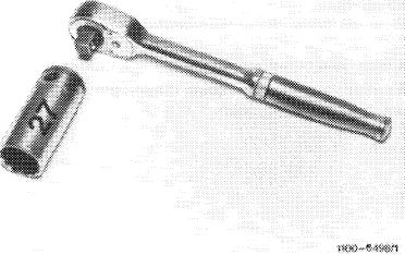
Socket 27 mm, 1/2″ square, for rotating engine
|
 |
001 589 65 09 00
|
||||
|
|
||||||
|
Dial gage holder
|
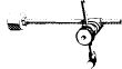 |
363 589 02 21 00
|
||||
|
11004-10150
|
||||||
|
|
||||||
|
Impact puller for bearing bolt (basic unit)
|
 |
116 589 20 33 00
|
||||
|
|
||||||
|
|
 |
|
||||
|
|
||||||
|
|
||||||
|
Note
|
||||||
|
|
||||||
|
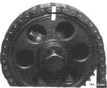
During assembly jobs, alignment of the markings (arrow) in ignition TDC position of 1st cylinder will be sufficient.
In special cases, e.g. during complaints about performance, check and adjust begin of opening at intake valve of 1st cylinder.
Timing is measured at 2 mm valve lift. For this purpose, the valve clearance must be neutralized.
|
 |
|||||
|
|
||||||
|
Checking
|
||||||
|
|
||||||
|
1 Unscrew pencil element glow plugs.
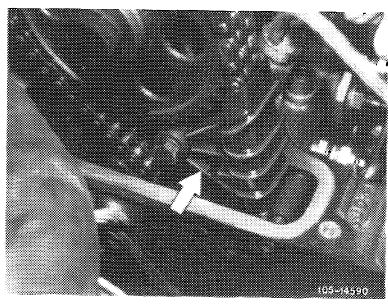
2 Disconnect regulating linkage to remove cylinder head cover. Pull out locking eye of longitudinal regulating shaft (arrow).
|
 |
|||||
|
Model 116.120
|
||||||
|
|
||||||
|
05.8-215/2 F2
|
||||||
|
|
||||||
|
|
|||
|
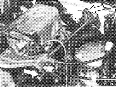
On models 116.120 and 123, pull longitudinal regulating shaft out of rubber mount in forward direction and remove in rearward direction.
On model 126.120, pull longitudinal regulating shaft out of guide lever in rearward direction and remove in forward direction.
|
 |
||
|
Model 123
|
|||
|
|
|||
|
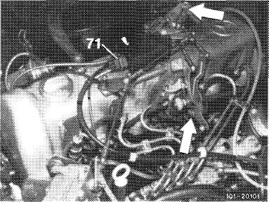
On models 123 with automatic transmission 722.303 (W 4 A 040) and 126.120, pull off central plug for vacuum lines (71) or vacuum lines. Disconnect Bowden wire, compress black plastic clip (arrow) and pull Bowden wire out of holder in rearward direction.
|
 |
||
|
Model 126.120
|
|||
|
|
|||
|
3 Rotate crankshaft with tool combination until cam tip is pointing upwards.
Attention!
Do not rotate engine on fastening screw of camshaft sprocket. Never rotate engine in reverse while measuring, since this will result in considerable measuring faults.
|
 |
||
|
|
|||
|
4 Just cancel valve clearance at intake valve of 1st cylinder by screwing up cap nuts (05—210).
|
 |
||
|
|
|||
|
05.8-215/3 F2
|
|||
|
|
|||
|
|
|||||||||||||||||||||||||||||||||||||||||||||||||||||||||||||||||||
|
5 Screw dial gage holder with threaded sleeve to stud at front right.
|
 |
||||||||||||||||||||||||||||||||||||||||||||||||||||||||||||||||||
|
|
|||||||||||||||||||||||||||||||||||||||||||||||||||||||||||||||||||
|
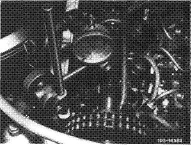
6 Insert dial gage and fasten in such a manner that the feeler pin rests on valve spring retainer at a preload of 3 mm (small needle of dial gage) (arrow).
Turn dial of dial gage until large needle rests on „0”.
Attention!
Feeler pin of dial gage should be seated on valve spring retainer in accurately vertical position.
7 Keep turning crankshaft in direction of rotation of engine until small needle of dial gage has gone back by 2 mm (valve lift) to 1 mm.
In this position, the value on balancing disk should be in agreement with the indicated value „intake valve opens”.
|
 |
||||||||||||||||||||||||||||||||||||||||||||||||||||||||||||||||||
|
|
|||||||||||||||||||||||||||||||||||||||||||||||||||||||||||||||||||
|
Adjustment
|
|||||||||||||||||||||||||||||||||||||||||||||||||||||||||||||||||||
|
|
|||||||||||||||||||||||||||||||||||||||||||||||||||||||||||||||||||
|
If the timing requires correction, install an offset Woodruff key or, if the chain is excessively elongated, install a new timing chain.
|
|||||||||||||||||||||||||||||||||||||||||||||||||||||||||||||||||||
|
|
|||||||||||||||||||||||||||||||||||||||||||||||||||||||||||||||||||
|
Woodruff keys are available in the following steps:
|
|||||||||||||||||||||||||||||||||||||||||||||||||||||||||||||||||||
|
|
|||||||||||||||||||||||||||||||||||||||||||||||||||||||||||||||||||
|
|||||||||||||||||||||||||||||||||||||||||||||||||||||||||||||||||||
|
|
|||||||||||||||||||||||||||||||||||||||||||||||||||||||||||||||||||
|
05.8-215/4 F2
|
|||||||||||||||||||||||||||||||||||||||||||||||||||||||||||||||||||
|
|
|||||||||||||||||||||||||||||||||||||||||||||||||||||||||||||||||||
|
|
|||
|
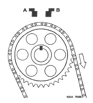
An offset by one tooth on camshaft sprocket results in approx. 18° at crankshaft.
An offset of Woodruff keys to the right (in driving direction [A]) results in an earlier begin of opening, and an offset to the left (B) in a later begin of opening.
|
 |
||
|
|
|||
|
8 Set engine to ignition TDC of 1st cylinder.
|
 |
||
|
|
|||
|
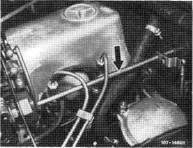
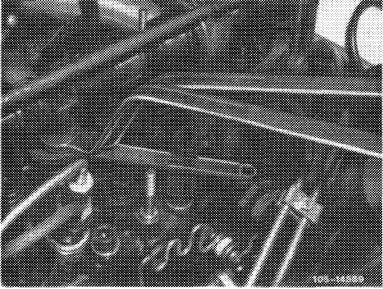
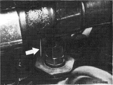
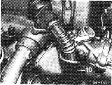
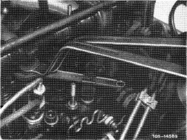
9 On engines with EGR (usa), remove pipe line between EGR valve and exhaust manifold (arrow). Unscrew shielding plate (10) for this purpose.
|
 |
||
|
|
|||
|
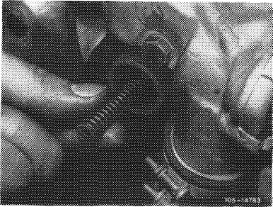
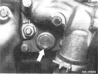
10 Unscrew closing plug of chain tensioner and remove compression spring (05—310).
|
 |
||
|
|
|||
|
05.8-215/5 F2
|
|||
|
|
|||
|
|
|||
|
11 Remove slide rail in cylinder head. Pull out bearing bolt by means of impact puller.
|
 |
||
|
|
|||
 |
|||
|
|
|||
|
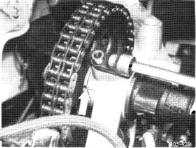
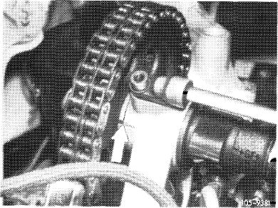
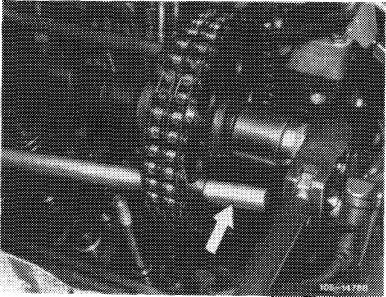
12 Mark camshaft sprocket and timing chain in relation to each other.
|
 |
||
|
|
|||
|
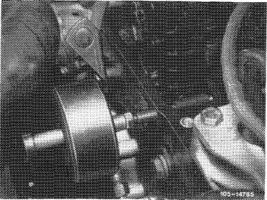
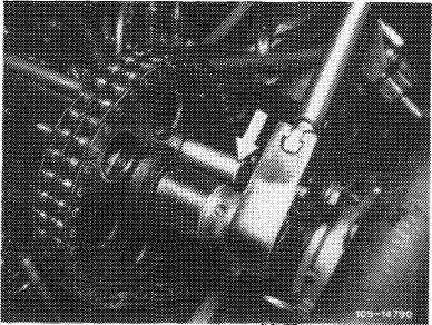
13 Remove camshaft sprocket.
To loosen necked-down screw of camshaft sprocket, apply counterhold with a screwdriver or steel pin.
|
 |
||
|
|
|||
|
05.8-215/6 F2
|
|||
|
|
|||
|
|
|||
|
14 Place rag under camshaft and remove Woodruff key.
15 Insert selected Woodruff key.
16 Mount camshaft sprocket while paying attention to color marks.
Do not tighten necked-down screw.
|
|||
|
|
|||
|
17 Repeat item 6 and 7.
18 Tighten necked-down screw for fastening camshaft sprocket to 80 Nm. For this purpose, apply counterhold to camshaft sprocket by means of a screwdriver or a steel pin.
19 Install slide rail.
|
 |
||
|
|
|||
|
20 Place compression spring into chain tensioner and tighten closing plug to 90 Nm.
|
 |
||
|
|
|||
|
21 Unscrew dial gage holder.
22 Adjust valve clearance at intake valve of 1st cylinder (05-210).
23 On engines with EGR <@), install pipe line between EGR valve and exhaust manifold. Screw on shielding plate.
24 Mount cylinder head cover.
|
 |
||
|
|
|||
|
05.8-215/7 F2
|
|||
|
|
|||