Operation injection pump with governor
|
|
|||||||||||||||||||||||||||||||||||||||||||||||||||||||||||||||||||||||
|
07.1—010 Operation injection pump with governor
|
|||||||||||||||||||||||||||||||||||||||||||||||||||||||||||||||||||||||
|
|
|||||||||||||||||||||||||||||||||||||||||||||||||||||||||||||||||||||||
|
Layout of injection pump
|
|||||||||||||||||||||||||||||||||||||||||||||||||||||||||||||||||||||||
|
|
|||||||||||||||||||||||||||||||||||||||||||||||||||||||||||||||||||||||
|
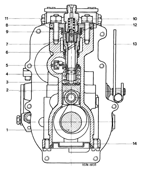
The layout of the injection pump is essentially the same as that of the M injection pump. On the other hand, the element assembly (12) is mounted to injection pump housing by means of holding flange (11).
The fastening nuts of the element assembly should never be loosened, since otherwise the basic adjustment of the respective element will be changed and renewed adjustment on the bench will be required.
|
|||||||||||||||||||||||||||||||||||||||||||||||||||||||||||||||||||||||
|
|
|||||||||||||||||||||||||||||||||||||||||||||||||||||||||||||||||||||||
|
 |
||||||||||||||||||||||||||||||||||||||||||||||||||||||||||||||||||||||
|
|
|||||||||||||||||||||||||||||||||||||||||||||||||||||||||||||||||||||||
|
|
|||
|
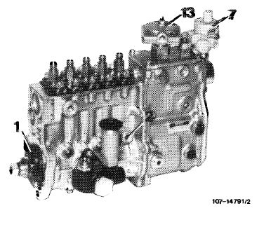
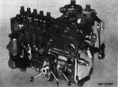
The injection pump is connected to engine oil circuit for lubrication.
The oil inlet (2) for lubrication is at 5th pump element. The oil flows through bores (1) on sealing flange of camshaft again back into crankcase.
|
 |
||
|
1 Oil outlet
2 Oil inlet
7 Vacuum control valve
13 ALDA housing
|
|||
|
|
|||
|
Relief throttle in pipe connection
|
|||
|
|
|||
|
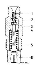
To reduce hydrocarbons in exhaust gas, relief throttles are installed in pipe connections of injection pump. The relief valve (2) is a platelet valve (3) opening in direction of injection nozzle with an orifice of 0.6 mm dia. The valve seat (4) is riveted into pipe connection. The relief valve permits the fuel to flow in direction of injection nozzle without obstruction. The pressure wave from injection nozzle in direction of injection pump, which is generated upon injection by the after-pumping effect of the nozzle needle when closing, is dampened by the relief throttle. This will prevent the pressure wave from subsequently flowing back to injection nozzle for re-injection. Re-injection will increase hydrocarbons in exhaust gas.
|
|||
|
|
|||
|
1 Compression spring
2 Relief throttle
3 Platelet valve
4 Valve seat
5 Pipe connection
6 Pressure valve carrier with pressure valve
|
 |
||
|
|
|||
|
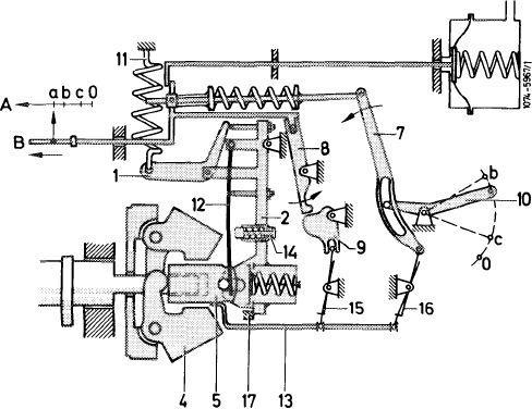
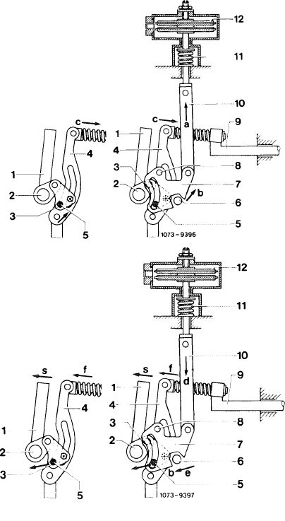
Layout and operation of RW-governor
The governor is a idle max. speed governor with its regulating spring (11) dimensioned and set in such a manner that the governor is not regulating in partial load range, except for the purpose of torque control (refer to „Throttle control during start and at full load”)
In partial load and full load range, the control rod (B) of the injection pump is operated by means of accelerator pedal only, which is connected to adjusting lever (10) of governor by means of the throttle linkage.
|
|||
|
|
|||
|
07.1.8-010/2 F3
|
|||
|
|
|||
|
|
|||||||||||||||||||||||||||||||||||||||||||||||||||||||||||||||||||||||||||
|
At increasing engine speed, as soon as the centrifugal force is higher than pressure of the regulating springs, the flyweights will move in outward direction. The movement of the flyweights is transmitted to control rod (B) by way of the sliding sleeve (5), the linkage (13) and the slotted lever (7).
As soon as max. speed is attained, the control rod is displaced in direction of stop. As a result, fuel delivery will be reduced and the engine speed will be limited. The procedure is reversed when the ingine speed drops.
|
|||||||||||||||||||||||||||||||||||||||||||||||||||||||||||||||||||||||||||
|
|
|||||||||||||||||||||||||||||||||||||||||||||||||||||||||||||||||||||||||||
|
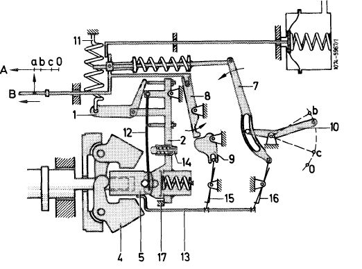
Governing procedure during start
|
|||||||||||||||||||||||||||||||||||||||||||||||||||||||||||||||||||||||||||
|
|
|||||||||||||||||||||||||||||||||||||||||||||||||||||||||||||||||||||||||||
|
In rest position, the swivel lever (2) is pushed to the left agains stop (17) under influence of regulating spring (11) and bell crank (1). In addition, the flyweights (4) are forced completely inward into their starting by means of the idle speed spring (12) via sliding sleeve (5).
|
|||||||||||||||||||||||||||||||||||||||||||||||||||||||||||||||||||||||||||
|
|
|||||||||||||||||||||||||||||||||||||||||||||||||||||||||||||||||||||||||||
|
 |
||||||||||||||||||||||||||||||||||||||||||||||||||||||||||||||||||||||||||
|
|
|||||||||||||||||||||||||||||||||||||||||||||||||||||||||||||||||||||||||||
|
When the accelerator pedal or the adjusting lever (10) are operated, the control rod (B) can be moved into starting position (a), since the excess fuel lock comprising cam (9) and sensor finger (8) is eliminated.
|
|||||||||||||||||||||||||||||||||||||||||||||||||||||||||||||||||||||||||||
|
|
|||||||||||||||||||||||||||||||||||||||||||||||||||||||||||||||||||||||||||
|
07.1.8-010/3 F3
|
|||||||||||||||||||||||||||||||||||||||||||||||||||||||||||||||||||||||||||
|
|
|||||||||||||||||||||||||||||||||||||||||||||||||||||||||||||||||||||||||||
|
|
|||||
|
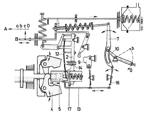
When the engine and thereby the camshaft of the injection pump are starting to rotate, the flyweights (4) will move away from each other. The sliding sleeve (5) will then be moved to the right together with linkage (13) against the spring pressure of the idle speed spring (12). The pin of the sliding sleeve is slidingly located in slot of swivel lever (2). This movement is transmitted to control rod by way of the connecting lever (16) and the slotted lever (7). Finger (8) will be swivelled out of cam (9) by way of the control rod.
|
|||||
|
|
|||||
|
1 Bell crank
2 Swivel lever
4 Flyweights
5 Sliding sleeve
7 Slotted lever
8 Finger
9 Cam
10 Adjusting lever
11 Regulating spring
12 Idle speed spring
|
13 Linkage
15 Connecting lever
16 Connecting lever
17 Stop
|
 |
|||
|
A B a b c
|
Control path Control rod Starting position Full load position Idle speed position
|
||||
|
|
|||||
|
As soon as the speed increases, the sliding sleeve (5) with linkage (13) and control rod (B) are each moving in the same direction, that is, a movement of the sliding sleeve to the right also makes the control rod move to the right. The injected fuel quantity is reduced, the engine speed will go down.
|
|||||
|
|
|||||
|
The adjusting lever (10) rests outside against resilient idle speed stop. (This may result in excess pressure against idle speed stop during manual shutoff.) In this position , the constant idle speed is regulated by the flyweights (4) together with the idle speed spring (12).
|
|||||
|
|
|||||
|
07.1.8-010/4 F2
|
|||||
|
|
|||||
|
|
|||||||||||||||||||||||||||||||||||||||||||||||||||||||||
|
 |
||||||||||||||||||||||||||||||||||||||||||||||||||||||||
|
|
|||||||||||||||||||||||||||||||||||||||||||||||||||||||||
|
At dropping speed, the flyweights (4) are forced inwards by the spring force of the idle speed spring (12). The sliding sleeve (5) and thereby the linkage (13) will then move to the left. The linkage will automatically shift control rod (B) also to the left under influence of connecting lever (16) and slotted lever (7), which means increased quantity and thereby an increase in speed.
The flyweights are again moving away from each other The sliding sleeve and thereby the control rod are moved to the right (less fuel injected) until the force of the flyweights and the spring force of the idle speed spring (12) are in equilibrium. As a result, an almost constant speed can be maintained also when adding the air-conditioning system, power steering and when engaging a driving position.
To dampen the idle speed, the swivel lever (2) is provided with an auxiliary idle speed spring (tickler 14), which pushes against idle speed spring starting at a given speed and thereby stabilizes the idle speed.
|
|||||||||||||||||||||||||||||||||||||||||||||||||||||||||
|
|
|||||||||||||||||||||||||||||||||||||||||||||||||||||||||
|
07.1.8-010/5 F2
|
|||||||||||||||||||||||||||||||||||||||||||||||||||||||||
|
|
|||||||||||||||||||||||||||||||||||||||||||||||||||||||||
|
|
|||||||||||||||||||||||||||||||||||||||||||||||||||||||||||||||||||||||||||||||||
|
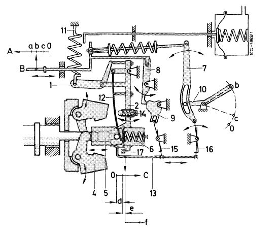
Full load and breakaway speed
|
|||||||||||||||||||||||||||||||||||||||||||||||||||||||||||||||||||||||||||||||||
|
|
|||||||||||||||||||||||||||||||||||||||||||||||||||||||||||||||||||||||||||||||||
|
In partial load and full load range the control rod (B) of the injection pump is operated by means of accelerator pedal only, which is connected to adjusting lever (10) of governor by way of the throttle linkage.
|
|||||||||||||||||||||||||||||||||||||||||||||||||||||||||||||||||||||||||||||||||
|
|
|||||||||||||||||||||||||||||||||||||||||||||||||||||||||||||||||||||||||||||||||
|
 |
||||||||||||||||||||||||||||||||||||||||||||||||||||||||||||||||||||||||||||||||
|
|
|||||||||||||||||||||||||||||||||||||||||||||||||||||||||||||||||||||||||||||||||
|
In full load position, the adjusting lever (10) rests outside against full load stop, that is, the control rod is at full load, which is the max. delivery quantity the engine can burn free of smoke.
The excess fuel lock comprising finger (8) and cam (9) serves to prevent that excess fuel is injected at full load and low speeds.
Regulation at full load and partial load begins at a given max. speed. The centrifugal force of the flyweights (4) is getting stronger than the pressure of the regulating speed (11) and swivel lever (2) will move from housing stop (17) to the right.
The resulting path of the sliding sleeve moves the control rod via the various transmission elements in direction of stop (0) until a given speed and injection quanty in accordance with the engine load is obtained.
|
|||||||||||||||||||||||||||||||||||||||||||||||||||||||||||||||||||||||||||||||||
|
|
|||||||||||||||||||||||||||||||||||||||||||||||||||||||||||||||||||||||||||||||||
|
07.1.8-010/6 F3
|
|||||||||||||||||||||||||||||||||||||||||||||||||||||||||||||||||||||||||||||||||
|
|
|||||||||||||||||||||||||||||||||||||||||||||||||||||||||||||||||||||||||||||||||
|
|
|||||||||||||||||||||||||||||||||||||||||||||||||||||||||
|
If the engine load is reduced with the adjusting lever position unchanged, the speed will increase up to no load max. speed. The P-degree (proportional degree) can be determined from the difference in speed between breakaway and end of regulation (no load max. speed).
Position between idle and full load speed regulation.
Except for torque control, there is no additional regulation in this range.
Torque control serves the purpose of feeding the engine the proportionally correct amount of injected fuel for each operating point on full load curve.
|
|||||||||||||||||||||||||||||||||||||||||||||||||||||||||
|
|
|||||||||||||||||||||||||||||||||||||||||||||||||||||||||
|
 |
||||||||||||||||||||||||||||||||||||||||||||||||||||||||
|
|
|||||||||||||||||||||||||||||||||||||||||||||||||||||||||
|
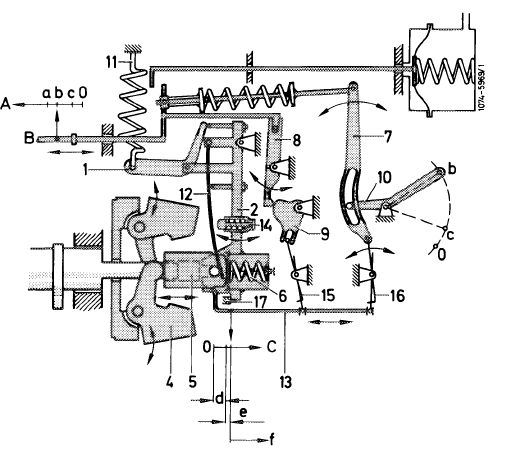
Prior to control the governor is once again in the position shown in illustration. The flyweights have applied excess pressure to idle speed spring (12) and torque control spring (6) via sliding sleeve (5), so that the sliding sleeve (5) rests rigidly against swivel lever (2). When the load on engine is increased, the speed will drop; the torque control spring (6) will slide the torque control pin resting on sliding sleeve (5) in outward direction and the flyweights will come together. The path which can be travelled by the torque control spring is restricted by a stop on torque control pin. The movement of the sleeve will push the control rod forward for a given distance (torque control path) via linkage (13) and slotted lever (7), so that the quantity of the injected fuel and the torque will be increased. The operating range of the torque control is determined by the preload of the torque control spring in torque control capsule and its rigidity.
|
|||||||||||||||||||||||||||||||||||||||||||||||||||||||||
|
|
|||||||||||||||||||||||||||||||||||||||||||||||||||||||||
|
07.1.8-010/7 F3
|
|||||||||||||||||||||||||||||||||||||||||||||||||||||||||
|
|
|||||||||||||||||||||||||||||||||||||||||||||||||||||||||
|
|
||||
|
Absolutely measuring boost pressure stop (ALDA)
The ALDA equipment serves to adapt the injected fuel quantity to the prevailing boost pressure and the respective altitude. As a result, the combustion chambers will always be provided with the correct injected fuel quantity for the pertinent cylinder charge, so that the best possible efficiency during the varying operating conditions will be obtained. The ALDA capsule is connected to the boost air pipe by means of a pressure line.
|
||||
|
|
||||
|
Enrichment by means of boost pressure (charge-air pressure)
|
||||
|
|
||||
|
The ALDA equipment comprises 2 aneroid capsules (12), a compression spring (11), a connecting rod (10) and the adjustable guide lever (7). The connecting rod (10) is connected to the control rod (9) by means of the adjustable guide lever (7), lever (3) and slotted lever (4). The increasing boost pressure compresses the aneroid capsules (12) and, supported by compression spring (11), the connecting rod (10) is pulled in direction „a”. As a result, the adjustable guide lever (7) will move within its adjusting range in direction „b” and will thereby push control rod (9) in direction „c” via coupling lever (3) and control lever (4). The injected fuel quantity will be increased.
|
 |
|||
|
ALDA with control equipment
|
||||
|
1 Adjusting lever
2 Adjusting lever shaft
3 Coupling lever
4 Control lever
5 Pin
6 Stop
7 Adjustable guide lever
|
8 Pivot (adjusting guide lever)
9 Control rod
10 Connecting rod
11 Compression spring
12 Aneroid capsules
|
|||
|
Altitude compensation
|
||||
|
During altitude operation, the aneroid capsules (12) will expand under influence of the reduced absolute pressure and will push connecting rod (10) in direction „d” against compression spring (11).
The ALDA adjustable guide lever (7) will automatically move in direction „e” and control rod (9) will consequently move over coupling lever (3) and control lever (4) in direction „f”. The injected fuel quantity will be reduced.
|
||||
|
07.1.8-010/8 F3
|
||||
|
|
||||
|
|
|||
|
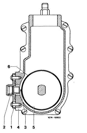
Reference impulse verification „RIV” for checking and adjusting injection timing (begin of delivery)
Instead of the static overflow method used up to now, injection timing (begin of delivery) can now be checked and adjusted with the engine running.
For this purpose, a flange (1) with closing plug (2) has been mounted outside on governor housing, and a lug (3) has been fitted to sheet metal bell (6).
|
 |
||
|
|
|||
|
1 Flange
2 Closing plug
3 Lug
4 Governor housing
5 Governor member
6 Sheet metal bell
|
 |
||
|
|
|||
|
Operation
Two signals are required to measure the association of the injection pump in relation to engine:
• TDC impulse from crankshaft.
• Regulating impulse from injection pump shaft.
|
|||
|
|
|||
|
07.1.8-010/9 F3
|
|||
|
|
|||
|
|
|||
|
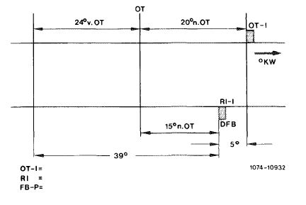
Both impulses are supplied by inductance transmitters. To obtain a measuring signal, the transmitter pins must be moved past the inductance transmitters at a minimum speed (idle speed). A measuring instrument measures the chronological distance of the two pulses and changes the result into an angle value, which is then indicated.
The highest measuring accuracy is attained, if the distance between the measuring impulses is relatively low.
|
|||
|
|
|||
|
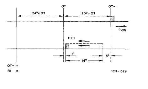
The position of the TDC transmitter is similar to gasoline engine 20 after TDC.
The regulating impulse of the injection pump has been set to 15° after TDC.
|
 |
||
|
OT-I TDC impulse Rl Regulating impulse
DFB Checking injection timing (begin of delivery)
|
|||
|
|
|||
|
Rl Regulating impulse OT-I TDC impulse
|
 |
||
|
|
|||
|
Injection timer
At increasing rpm the injection timer will set the regulating impulse in the direction of advance. The measuring value for injection timing (begin of delivery) is getting smaller and attains approx. 0°—1° at max. adjustment.
|
|||
|
|
|||
|
07.1.8-010/10 F3
|
|||
|
|
|||