Operation engine-transmission-overload protection
|
|
||||||
|
07.1—015 Operation engine-transmission-overload protection
|
||||||
|
|
||||||
|
Engine-transmission overload protection
To prevent damage to engine and transmission in the event of faulty operation or during extreme situations the engine-transmission overload protection performs 3 functions:
1. Engine overload protection.
2. Transmission overload protection.
3. Shifting-down automatic transmission into 1st gear when moving off.
|
||||||
|
|
||||||
 |
||||||
|
|
||||||
|
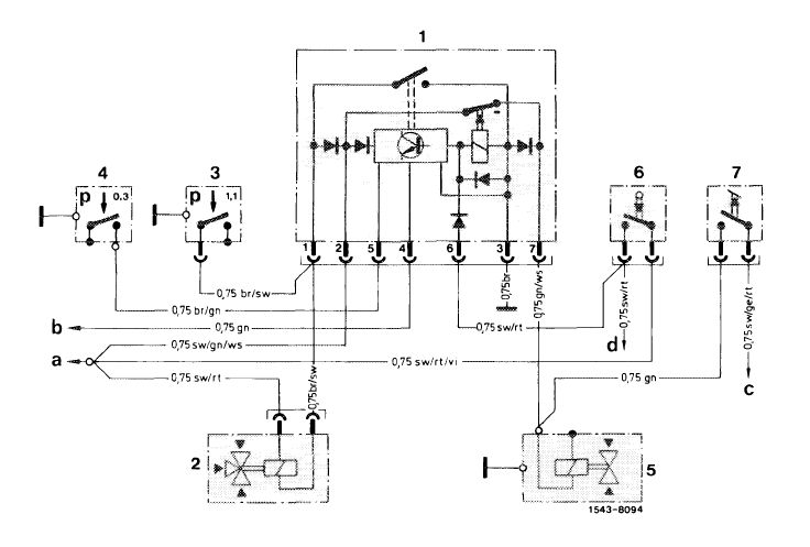
Circuit diagram engine-, transmission-overload switch — Model 116.120
|
model year 1978—1980
|
|||||
|
|
||||||
|
1 Switching unit overload protection
2 Changeover valve
3 Pressure switch boost air pipe
4 Pressure switch transmission
|
5 Solenoid valve automatic transmission
6 Stop lamp switch
7 Kickdown switch
|
a To fuse no. 4 b To revolution
counter c To clutch starter
lockout switch d To stop lamps
|
||||
|
|
||||||
|
07.1.8-015/1
|
F 3
|
|||||
|
|
||||||
|
|
||||
 |
||||
|
|
||||
|
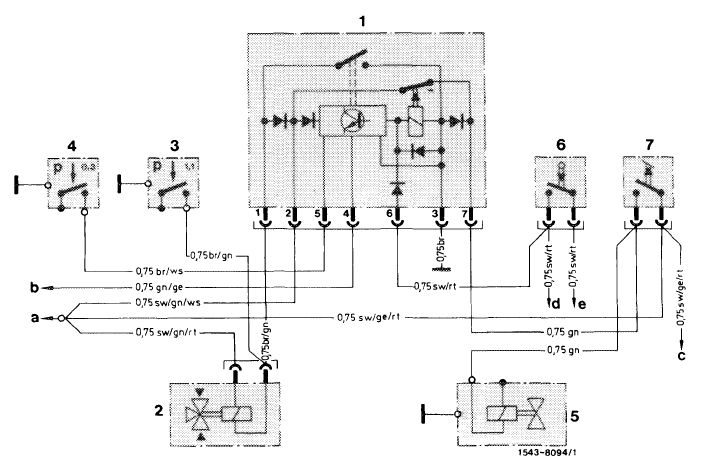
Circuit diagram engine-transmission overload switch — Model 123.193 standard version
|
||||
|
|
||||
|
1 Switching unit overload protection
2 Changeover valve
3 Pressure switch boost air pipe
4 Pressure switch transmission
|
5 Solenoid valve automatic transmission
6 Stop lamp switch
7 Kickdown switch
|
a To fuse no. 4 b To revolution
counter c To clutch starter
lockout switch d To stop lamp
switch
|
||
|
|
||||
|
07.1.8-015/2 F3
|
||||
|
|
||||
|
|
||||
|
Engine overload protection
|
||||
|
|
||||
|
Model 123.193 Model 126.120
|
starting model year 1981
|
|||
|
|
||||
|
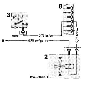
Starting model year 1981, installation of transmission 722.303 instead of 722.120 has made the transmission overload protection unnecessary. Only an engine overload protection will be installed.
|
||||
|
|
||||
|
Circuit diagram engine overload protection
2 Changeover valve boost air pipe
3 Pressure switch boost air pipe a To fuse no. 10 (terminal 15)
|
 |
|||
|
|
||||
|
07.1.8-015/3 F3
|
||||
|
|
||||
|
|
|||
|
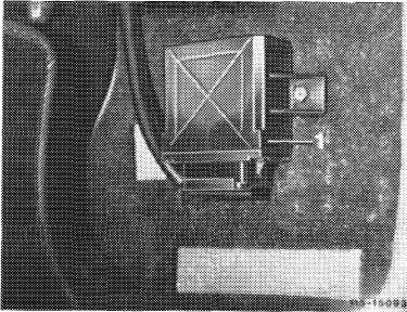
Engine overload protection
|
 |
||
|
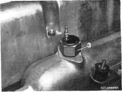
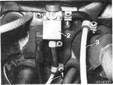
The boost air pipe is provided with a pressure switch (3) At a boost pressure above 1.1 ± 0,15 bar gauge pressure, the pressure switch will close and will connect minus (negative) to changeover valve (2), which is connected to plus (positive) via terminal 15. The changeover valve interrupts the connection boost air pipe to ALDA aneroid capsule on injection pump. The aneroid capsule is connected to atmosphere and the injection fuel quantity is thereby reduced. If the pressure drops to below 1.1 ± 0.15 bar gauge pressure, the pressure switch will again interrupt the minus (negative) connection and will connect the ALDA aneroid capsule again to boost air pipe.
|
|||
|
|
|||
|
Model 116
|
 |
||
|
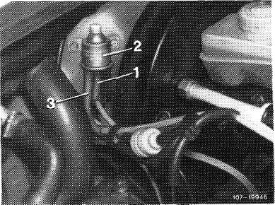
1 Pressure line of boost air pipe
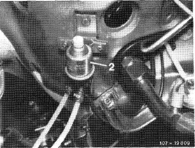
2 Changeover valve
3 Pressure line to ALDA capsule
|
|||
|
|
|||
|
Model 123
|
 |
||
|
|
|||
|
Model 126
|
 |
||
|
|
|||
|
07.1.8-015/4 F2
|
|||
|
|
|||
|
|
|||
|
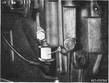
Transmission overload protection
|
 |
||
|
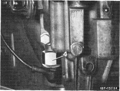
If the pressure switch (4) is subject to a pressure below 0.3 bar gauge pressure (driving speed below approx. 8 km/h) and if the engine speed rises to above approx. 2000/min, e.g.when moving off on a high gradient with a fully loaded vehicle, the transmission may become overloaded by the high torque. A reduction of the injected fuell quantity on injection pump will prevent an engine speed increase obove approx. 2000/min.
|
|||
|
|
|||
|
The rpm switch in switching unit activates the changeover valve with minus (negative). Since terminal 15 provides a connection to plus (positive), the valve will switch and will provide the pressure line to ALDA capsule on injection pump with ambient pressure. This will reduce the injected fuel quantity, the engine speed will drop below 2000/min (by approx. 100/mtn). If engine speed drops below approx. 2000/min, the rpm switch in switching unit (1) will interrupt the minus (negative) connection at changeover valve. The valve opens the connection to boost air pipe and will close the connection of pressure line to the atmosphere. The reduction of the injected fuel quantity is cancelled and the engine speed will increase again. This regulating cycle will be repeated until the pressure at switch (4) has attained 0.3 bar gauge pressure. The pressure switch will then close and the overload protection is thereby disconnected.
|
 |
||
 |
|||
|
|
|||
|
07.1.8-015/5 F2
|
|||
|
|
|||