Removal and installation of valve springs
|
|
|||||||||||||||||||||||||||||||
|
05—250 Removal and installation of valve springs
|
|||||||||||||||||||||||||||||||
|
|
|||||||||||||||||||||||||||||||
|
Valve clearance
|
with engine cold (approx. 20
|
with engine warm (60 °C ± 15
|
|||||||||||||||||||||||||||||
|
|
|||||||||||||||||||||||||||||||
|
Intake
|
0.101)
|
0.151)
|
|||||||||||||||||||||||||||||
|
|
|||||||||||||||||||||||||||||||
|
Exhaust
|
0.35
|
0.40
|
|||||||||||||||||||||||||||||
|
|
|||||||||||||||||||||||||||||||
|
M 0.05 mm higher during lasting outside temperatures below —20 °C.
|
|||||||||||||||||||||||||||||||
|
|
|||||||||||||||||||||||||||||||
|
|||||||||||||||||||||||||||||||
|
|
|||||||||||||||||||||||||||||||
|
Valve adjusting wrench 14 mm (2 each)
|
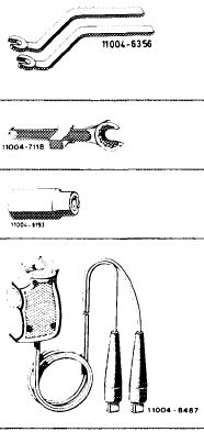 |
615 589 00 01 00
|
|||||||||||||||||||||||||||||
|
Holding wrench for valve spring retainer
|
615 589 00 03 00
|
||||||||||||||||||||||||||||||
|
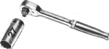
Socket 27 mm, 1/2″ square, for rotating engine
|
001 589 65 09 00
|
||||||||||||||||||||||||||||||
|
Contact handle for rotating engine (component of compression pressure recorder 001 589 46 21 00)
|
001 589 46 21 08
|
||||||||||||||||||||||||||||||
|
|
|||||||||||||||||||||||||||||||
|
Note
|
 |
||||||||||||||||||||||||||||||
|
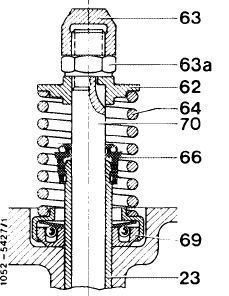
Each valve has one valve spring (64) and one rotocap (69).
On engines with long service life, it is recommended to renew rotocaps at the same time.
|
|||||||||||||||||||||||||||||||
|
23 Valve guide 66 Valve stem seal
62 Valve spring retainer 69 Rotocap
63 Cap nut 70 Valve 63a Counternut
64 Valve spring
|
|||||||||||||||||||||||||||||||
|
|
|||||||||||||||||||||||||||||||
|
05.8-250/1 F 2
|
|||||||||||||||||||||||||||||||
|
|
|||||||||||||||||||||||||||||||
|
|
||||
|
Valve springs with higher spring tension are installed on engine 617.950 since January 1979 and on engines 617.951/952 since start of series (05-260).
On engine 617.950 (usa) starting model year 1980 with increased output and on engines 617.951/952, do not install valve spring, part No. 180 053 06 20.
On the other hand, on engine 617.950 (usa) up to model year 1980 with increased output, valve spring part No. 615 053 01 20 may also be installed.
|
||||
|
|
||||
|
Start of series
|
||||
|
|
||||
|
Engine
|
Starting chassis No.
|
|||
|
|
||||
|
617.950 617.951/952
|
006303 start of series
|
|||
|
|
||||
|
Identification:
Valve spring, part No. 180 053 06 20, two green or purple-green color dots.
Valve spring, part No. 615 053 01 20, two yellow or purple-yellow color dots.
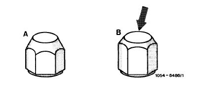
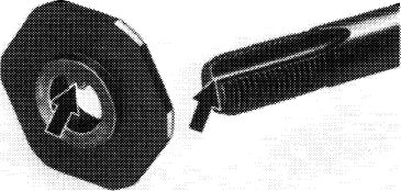
Renew damaged cap nuts (63).
Cap nuts are available in three versions:
|
||||
|
|
||||
|
1st version
|
||||
|
|
||||
|
Cap nut with small supporting surface (A).
|
||||
|
|
||||
|
2nd version
Cap nut reinforced in upper range, with larger supporting surface (B).
|
||||
|
|
||||
|
3rd version
|
||||
|
|
||||
|
Cap nut reinforced in upper range and hard-chromed.
|
 |
|||
|
Identification: silver colored.
|
||||
|
|
||||
|
05.8-250/2 F 2
|
||||
|
|
||||
|
|
|||
|
On engines with chilled cast iron camshaft and rocker arms with carbide facing, only the hard-chromed cap nut may be installed.
The hard-chromed cap nut can also be installed on engines with chilled cast iron camshafts and rocker arms with inductance-hardened and hard-chromed running surface.
Spare parts (ET) Sindelfingen will keep only hard-chromed cap nuts in stock.
|
|||
|
|
|||
|
Removal
|
 |
||
|
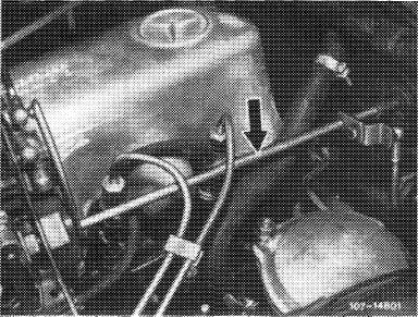
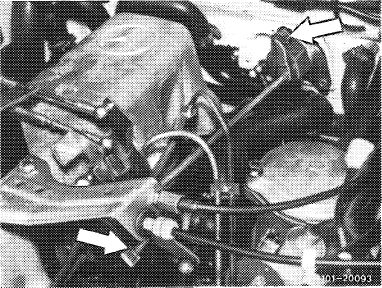
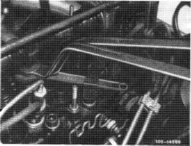
1 Disconnect regulating linkage to remove cylinder head cover. Pull out locking eye of longitudinal regulating shaft (arrow).
|
|||
|
Model 116.120
|
|||
|
|
|||
|
On models 116.120 and 123, pull longitudinal regulating shaft out of rubber mount in forward direction and remove in rearward direction.
On model 126.120 pull longitudinal regulating shaft out of guide lever in rearward direction and remove in forward direction.
|
 |
||
|
Model 123
|
|||
|
|
|||
|
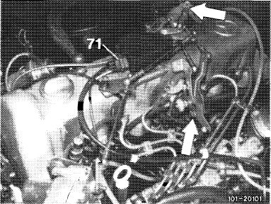
On models 123 with automatic transmission 722.303 (W 4 A 040) and 126.120, disconnect central plug for vacuum lines (71) or vacuum lines. Disconnect Bowden wire, compress black plastic clip (arrow) and pull Bowden wire out of holder in rearward direction.
|
 |
||
|
Model 126.120
|
|||
|
|
|||
|
05.8-250/3 F 2
|
|||
|
|
|||
|
|
|||
|
2 Remove rocker arm with rocker arm bearing brackets (05-235).
|
 |
||
|
|
|||
|
3 Set piston of respective cylinder to ignition TDC.
For this purpose, rotate crankshaft with tool combination.
|
 |
||
|
|
|||
|
1100-6498/1
|
|||
|
|
|||
|
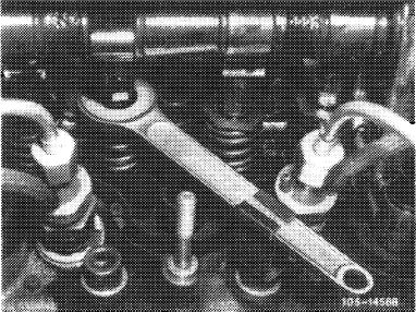
4 Place holding wrench on valve spring retainer.
|
 |
||
|
|
|||
|
5 Unscrew cap nut (63) by means of valve adjusting wrench.
For this purpose, apply counterhold to counternut (63a) by means of second valve adjusting wrench.
6 Unscrew counternut (63a).
7 Remove valve spring retainer and valve spring.
8 Check valve spring, renew according to condition (05-260).
|
 |
||
|
|
|||
|
05.8-250/4 F 2
|
|||
|
|
|||
|
|
||||
|
Installation
|
 |
|||
|
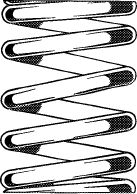
9 Insert valve spring with narrow coils toward cylinder head (color dots at top).
|
||||
|
|
||||
|
1054-7671
|
||||
|
|
||||
|
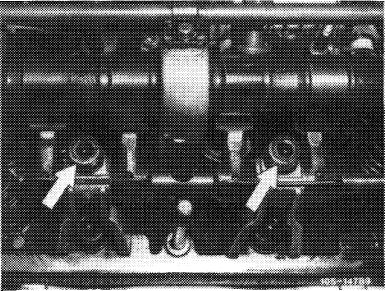
10 Mount valve spring retainer.
Lug on valve spring retainer (arrow) should be seated in groove on valve stem.
11 Screw on counternut and cap nut.
12 Install rocker arm with rocker arm bearing brackets (05-235).
13 Adjust valve clearance (05—210).
14 Mount cylinder head cover.
|
 |
|||
|
|
||||
|
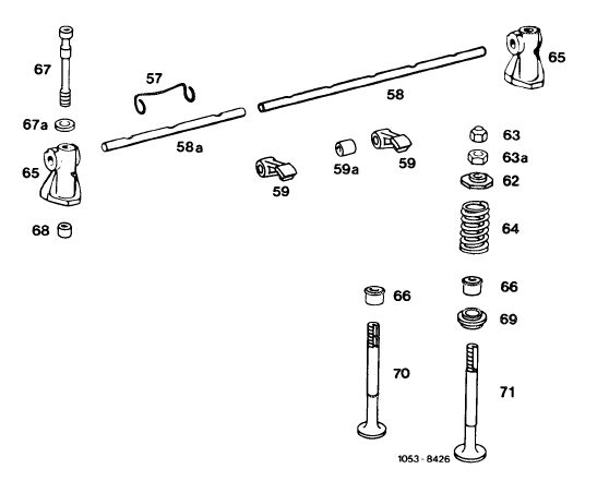
Valve timing
|
||||
|
|
||||
 |
||||
|
|
||||
|
57 Tensioning spring
58 Rocker arm shaft 58a Rocker arm shaft
59 Rocker arm
59a Rocker arm bearing bushing
62 Valve spring retainer
63 Cap nut 63a Counternut
64 Valve spring
|
65 Bearing bracket
66 Valve shaft seals
67 Screw 67a Washer
68 Fitted sleeve
69 Rotocap
70 Intake valve
71 Exhaust valve
|
|||
|
|
||||
|
05.8-250/5 F 2
|
||||
|
|
||||