Measuring, boring and honing cylinder bores
|
|
||||||||||||||||||||||||||||
|
01—110 Measuring, boring and honing cylinder bores
|
||||||||||||||||||||||||||||
|
|
||||||||||||||||||||||||||||
|
Coordination piston — cylinder
|
||||||||||||||||||||||||||||
|
|
||||||||||||||||||||||||||||
|
||||||||||||||||||||||||||||
|
|
||||||||||||||||||||||||||||
|
Cylinder bore
|
||||||||||||||||||||||||||||
|
|
||||||||||||||||||||||||||||
|
Max. wear limit in forward or transverse direction
|
0.10
|
|||||||||||||||||||||||||||
|
|
||||||||||||||||||||||||||||
|
when new
|
0.014
|
|||||||||||||||||||||||||||
|
|
||||||||||||||||||||||||||||
|
Permissible out-of-true and conicity
|
||||||||||||||||||||||||||||
|
|
||||||||||||||||||||||||||||
|
wear limit
|
0.05
|
|||||||||||||||||||||||||||
|
|
||||||||||||||||||||||||||||
|
Permissible deviation vertically in relation to crankshaft center line, with reference to cylinder height
|
0.05
|
|||||||||||||||||||||||||||
|
|
||||||||||||||||||||||||||||
|
Permissible roughness
|
0.002-0.004
|
|||||||||||||||||||||||||||
|
|
||||||||||||||||||||||||||||
|
Permissible waviness
|
50 % of roughness
|
|||||||||||||||||||||||||||
|
|
||||||||||||||||||||||||||||
|
Honing angle
|
25C
|
|||||||||||||||||||||||||||
|
|
||||||||||||||||||||||||||||
|
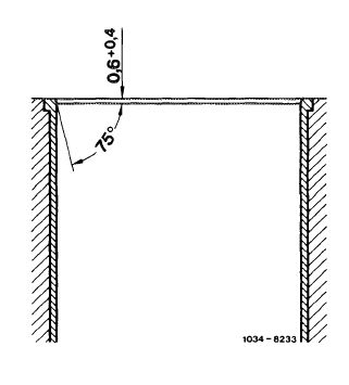
Chamfer of cylinder bores
|
refer to Fig.
|
|||||||||||||||||||||||||||
|
|
||||||||||||||||||||||||||||
|
1 These engines have no repair steps.
|
||||||||||||||||||||||||||||
|
|
||||||||||||||||||||||||||||
|
Note
|
||||||||||||||||||||||||||||
|
|
||||||||||||||||||||||||||||
|
In addition of a visual checkup, in particular in the event of complaints about „high oil consumption” measuring of cylinder bores is unavoidable.
|
||||||||||||||||||||||||||||
|
|
||||||||||||||||||||||||||||
|
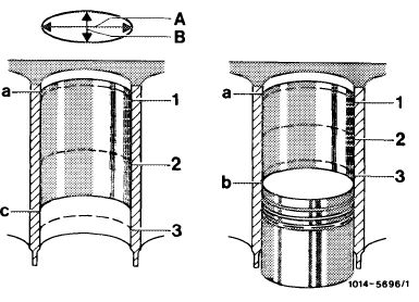
For this purpose, measure the clean cylinder bores with internal measuring instrument at measuring points, 1, 2 and 3 in longitudinal direction A (piston pin center line) and in transverse direction B.
With piston installed, the measuring point 3 is barely above piston, at BDC.
|
 |
|||||||||||||||||||||||||||
|
a Upper reversing point of 1st piston ring
b BDC of piston
c Lower reversing point of oil scraper ring
|
||||||||||||||||||||||||||||
|
|
||||||||||||||||||||||||||||
|
01.8-110/1 F2
|
||||||||||||||||||||||||||||
|
|
||||||||||||||||||||||||||||
|
|
|||
|
Chamfer cylinder bores after boring.
For honing, the material allowance should not exceed 0.03 mm.
|
 |
||
|
|
|||
|
01.8-110/2 F2
|
|||
|
|
|||