Renewing, boring and honing cylinder liners
|
|
||||||||||||||||||||||||||||||||||||||||||||||
|
01—115 Renewing, boring and honing cylinder liners
|
||||||||||||||||||||||||||||||||||||||||||||||
|
|
||||||||||||||||||||||||||||||||||||||||||||||
|
Coordination piston — cylinder
|
||||||||||||||||||||||||||||||||||||||||||||||
|
|
||||||||||||||||||||||||||||||||||||||||||||||
|
||||||||||||||||||||||||||||||||||||||||||||||
|
|
||||||||||||||||||||||||||||||||||||||||||||||
|
Cylinder crankcase
|
||||||||||||||||||||||||||||||||||||||||||||||
|
|
||||||||||||||||||||||||||||||||||||||||||||||
|
||||||||||||||||||||||||||||||||||||||||||||||
|
|
||||||||||||||||||||||||||||||||||||||||||||||
|
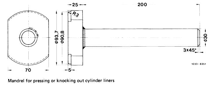
Self-made tool
|
||||||||||||||||||||||||||||||||||||||||||||||
|
|
||||||||||||||||||||||||||||||||||||||||||||||
 |
||||||||||||||||||||||||||||||||||||||||||||||
|
|
||||||||||||||||||||||||||||||||||||||||||||||
|
01.8-115/1 F2
|
||||||||||||||||||||||||||||||||||||||||||||||
|
|
||||||||||||||||||||||||||||||||||||||||||||||
|
|
|||
|
Note
Always install approved cylinder liners only (refer to spare parts data).
Owing to different manufacturers, the cylinder liners are identified with notches at lower edge.
1 notch = Teves; 2 notches = Pleuco;
3 notches = Wizemann; 4 notches = Brico
|
|||
|
|
|||
|
Renewal
|
|||
|
|
|||
|
1 Press out cylinder liners with self-made mandrel and a press or knock out with a hammer.
2 Thoroughly clean basic bore.
|
 |
||
|
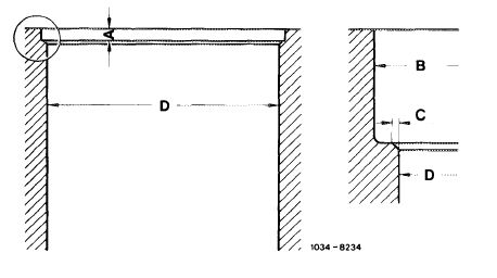
A = 4.3-4.6 mm
B = 96.02-96.08 mm
C = 0.25-0.35 mm
D = 94.000-94.035 mm
|
|||
|
|
|||
|
3 Measure basic bore (D) in cylinder crankcase.
If the out-of-true condition exceeds 0.1 mm, do not use cylinder crankcase any longer.
|
|||
|
|
|||
|
4 Position new cylinder liners. Place steel plate of pertinent size on liner flange and press-in liner with a press or knock in with a hammer.
After pressing or knocking in cylinder liner, leave for another approx. 7 seconds under press (setting pressure) or add a few setting blows with hammer.
|
|||
|
|
|||
|
01.8-115/2 F2
|
|||
|
|
|||
|
|
|||
|
5 Mill or grind off projecting liner flange. Remove as little as possible from cylinder crankcase parting surface. Guide milling cutter or grinding wheel centrally over cylinder bores.
6 Enlarge cylinder liner bores in two steps. For honing, leave an allowance of 0.03 mm in bores.
|
 |
||
|
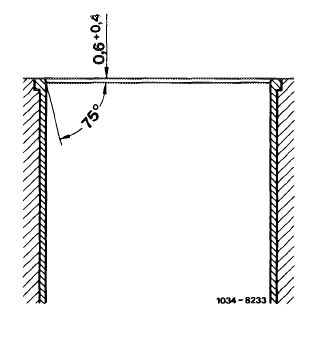
7 Chamfer cylinder liners.
8 Hone cylinder bores.
9 Measure cylinder bores and select pertinent pistons (02-316).
|
|||
|
|
|||
|
01.8-115/3 F2
|
|||
|
|
|||