Machining valve seats
|
|
|||||||||||||||||||||||||
|
05—291 Machining valve seats
|
|||||||||||||||||||||||||
|
|
|||||||||||||||||||||||||
|
Data
|
Intake
|
Exhaust
|
|||||||||||||||||||||||
|
|
|||||||||||||||||||||||||
|
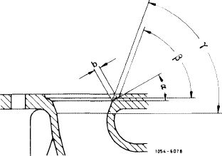
Valve seat width b
|
1.3-1.6
|
2.5-2.9
|
 |
||||||||||||||||||||||
|
|||||||||||||||||||||||||
|
Permissible runout of valve seat
|
0.03
|
||||||||||||||||||||||||
|
|
|||||||||||||||||||||||||
|
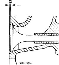
Minimum distance „a” with new valves and new valve seats
|
 |
||||||||||||||||||||||||
|
Intake
|
+ 0.17 to-0.23
|
||||||||||||||||||||||||
|
Exhaust
|
+ 0.12 to -0.28
|
||||||||||||||||||||||||
|
Maximum distance „a” with new valves and machined (ref inished) valve seats
|
|||||||||||||||||||||||||
|
Intake
|
1.0
|
||||||||||||||||||||||||
|
|
|||||||||||||||||||||||||
|
Exhaust
|
|||||||||||||||||||||||||
|
|
|||||||||||||||||||||||||
|
The max. distance is reduced by the same amount by which the cylinder head parting surface has been ref inished.
|
|||||||||||||||||||||||||
|
|
|||||||||||||||||||||||||
|
Valve stem wear (wear limit)
|
0.05
|
||||||||||||||||||||||||
|
|
|||||||||||||||||||||||||
|
Special tools
|
|||||||||||||||||||||||||
|
|
|||||||||||||||||||||||||
|
Valve adjusting wrench 14 mm (2 each)
|
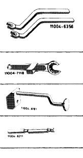 |
615 589 00 01 00
|
|||||||||||||||||||||||
|
Holding wrench for valve spring retainer
|
615 589 00 03 00
|
||||||||||||||||||||||||
|
Assembly mandrel for valve stem seals Intake and exhaust
|
617 589 00 43 00
|
||||||||||||||||||||||||
|
Plug gage 10 mm dia. for intake and exhaust valve guide
|
615 589 00 21 00
|
||||||||||||||||||||||||
|
|
|||||||||||||||||||||||||
|
05.8-291/1 F2
|
|||||||||||||||||||||||||
|
|
|||||||||||||||||||||||||
|
|
|||
|
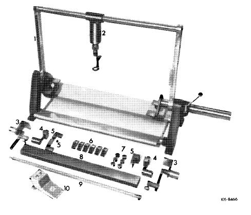
Conventional tools
|
|||
|
|
|||
|
Cylinder head clamping fixture
|
e.g. made by Christ, D-6801 Neckarhausen Order No. DBK 60-2
|
||
|
|
|||
|
Valve seat machining tool
|
e.g. made by Hunger, D-8000 Miinchen Type VDNSL 1/45/30, order No. 236.03.308
|
||
|
|
|||
|
Test kit for valve seats
|
e.g. made by Hunger, D-8000 Munchen Order No. 216.93.300
|
||
|
|
|||
|
Note
|
 |
||
|
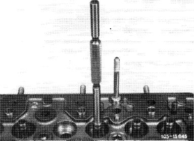
Clamp cylinder head into clamping fixture for disassembly and machining.
Machine valve seats with valve machining tool, with valve seat grinding machine or with valve seat milling cutter.
|
|||
|
|
|||
|
Machining valve seats
|
|||
|
|
|||
|
1 Check valve guides and replace, if required (05-285).
|
 |
||
|
|
|||
|
05.8-291/2 F2
|
|||
|
|
|||
|
|
|||
|
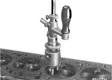
2 Machine valve seat (30°) (refer to operating instructions of tool manufacturer).
Attention!
Release pilot (013) only after runout of valve seat has been checked.
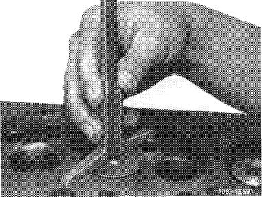
3 Measure valve seat width b and correct below to 60°, if required.
If required, also correct clearance (/3) to 60°.
|
 |
||
|
|
|||
|
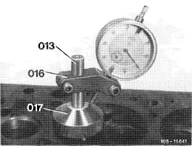
4 Check runout of valve seat.
|
 |
||
|
For this purpose, slip test sleeve (017) with dial gage holder (016) and dial gage on pilot (013) and rotate test sleeve. The permissible runout of 0.03 mm should then not be exceeded.
|
|||
|
013 Pilot
016 Dial gage holder
017 Test sleeve
|
|||
|
|
|||
|
5 Introduce new valve and measure max. distance a.
|
 |
||
|
|
|||
|
05.8-291/3 F2
|
|||
|
|
|||